
Abstract
This study aims to analyze the steady-state temperature field and thermal deformation field of electric drive helical gears. Based on the meshing principle of helical gears and the theories of heat transfer and tribology, the average friction heat flux on the meshing surface and the convective heat transfer coefficients of other surfaces are derived. A parametric thermal analysis model of the helical gear is established using the APDL language, providing insights into the influence of different gear models on the steady-state temperature field and thermal deformation field. The results indicate that the temperature field varies gradually, with the highest temperature occurring on the meshing surface and the lowest on the hub. The deformation is most significant at the tooth tip and least at the hub, with the maximum deformation observed near the ends of the gear. To reduce computational costs, the single-tooth model can be used with high accuracy for steady-state temperature analysis, but only the full-tooth model provides accurate results for thermal deformation analysis.
Keywords: helical gear, finite element method, steady-state temperature field, thermal deformation field
Introduction
Helical gears are widely used in electric drive systems due to their excellent transmission performance and load-bearing capacity. However, during operation, significant heat is generated at the meshing interface due to axial and radial sliding friction, particularly under high-speed and heavy-load conditions. This heat can lead to adhesion failure and thermal deformation, which alters the involute tooth profile, thereby affecting the gear’s meshing characteristics and potentially causing vibration and noise. Therefore, studying the temperature field and thermal deformation field of electric drive helical gears is crucial.
Several methods exist for analyzing gear temperature fields and thermal deformation fields, including numerical calculations, experimental analysis, and finite element methods (FEM). This study employs FEM to establish a parametric thermal analysis model of helical gears using the APDL (ANSYS Parametric Design Language) and investigates the influence of different gear models on the accuracy of the results.
Theoretical Background
Meshing Principle of Helical Gears
Helical gears transmit power through the gradual engagement of their teeth. As the teeth mesh, heat is generated due to friction at the contact points. This heat is then distributed through the gear body and dissipated via convection with the surrounding environment and the lubricant.
Heat Transfer Theory
The steady-state temperature field of a helical gear can be described using the heat conduction equation based on Fourier’s law of heat conduction:
lambda(∂x2∂2T+∂y2∂2T+∂z2∂2T)=0
where T is the temperature and λ is the thermal conductivity.
Boundary Conditions
The boundary conditions of the gear surfaces are critical for solving the heat conduction equation. These conditions can be expressed using Newton’s law of cooling and Fourier’s law of heat conduction:
- Meshing Surface: A combination of second- and third-type boundary conditions, given by:−λ(∂n∂T)=s1(Tc−To)−qw
- Non-Meshing Surfaces, Tips, Roots, and Ends: Third-type boundary conditions, given by:−λ(∂n∂T)=s2(Tc−To)
where s1 and s2 are the convective heat transfer coefficients, Tc and To are the initial temperatures of the gear and lubricant, respectively, and qw is the average friction heat flux.
Calculation of Friction Heat Flux and Convective Heat Transfer Coefficients
Average Friction Heat Flux
The average friction heat flux on the meshing surface is calculated using:
qj=T1πkfμPMfτ0(v1−v2)
where kf is the heat flux distribution coefficient, μ is the friction coefficient, PM is the maximum Hertz contact pressure, f is the thermal conversion factor, τ0 is the half-bandwidth of time-domain contact, v1 and v2 are the tangential velocities of the driving and driven gears, respectively, and T1 is the meshing period of the driving gear.
Convective Heat Transfer Coefficients
- Tooth Tip:hd=0.664λoPo0.333(νoω)0.5
- Tooth Flank and Root:ha=0.228Re0.731ePo0.333Ldλo
- Ends: Depending on the Reynolds number (( Re )), the convective heat transfer coefficient can be calculated as:h_t = \begin{cases} 0.308 \lambda_{mix} (m_z + 2)^{0.5} P_{mix}^{0.5} \left( \frac{\omega}{\nu_{mix}} \right)^{0.5}, & \text{if } Re \leq 2 \times 10^5 \\ 10^{-19} \lambda_{mix} \left( \frac{\omega}{\nu_{mix}} \right)^4 r_n^7, & \text{if } 2 \times 10^5 < Re \leq 2.5 \times 10^5 \\ 0.0197 \lambda_{mix} (m_z + 2.6)^{0.2} \left( \frac{\omega}{\nu_{mix}} \right)^{0.8} r_n^{0.6}, & \text{if } Re > 2.5 \times 10^5 end{cases}
where λo, ρo, co, and νo are the thermal conductivity, density, specific heat capacity, and kinematic viscosity of the lubricant, respectively; Re is the Reynolds number; and ω is the angular velocity of the gear.
Finite Element Model
Gear and Lubricant Parameters
The parameters of the helical gear and lubricant used in this study are listed in Tables 1 and 2, respectively.
Table 1: Helical Gear Parameters
| Parameter | Value |
|---|---|
| Driving Gear Speed | 2000 rpm |
| Elastic Modulus | 206 GPa |
| Number of Teeth (z1) | 23 |
| Number of Teeth (z2) | 30 |
| Poisson’s Ratio | 0.3 |
| Modulus (m) | 3 mm |
| Pressure Angle (α) | 20° |
| Thermal Conductivity | 46 W/m·K |
| Specific Heat | 465 J/kg·K |
| Density | 7850 kg/m³ |
| Helix Angle (β) | 8° |
| Input Power (P) | 50 kW |
Table 2: Lubricant Parameters
| Parameter | Value |
|---|---|
| Lubricant Type | SCH632 |
| Density (ρ_o) | 870 kg/m³ |
| Kinematic Viscosity (ν_o) | 320 cSt (at 40°C), 38.5 cSt (at 100°C) |
| Thermal Conductivity (λ_o) | 2000 W/m·K |
| Specific Heat (c_o) | 0.14 J/kg·K |
Modeling and Meshing
A parametric thermal analysis model of the helical gear was created using the APDL language in ANSYS. The gear was meshed using 8-node hexahedral elements (Solid70), with the friction heat flux applied using surface effect elements (Surf152). the full-tooth parametric model of the helical gear.
Results and Discussion
Steady-State Temperature Field
The steady-state temperature field of the driving gear, obtained using the full-tooth model. The highest temperature (92.4488°C) is observed on the meshing surface, with the lowest temperature on the hub.
Temperature Distribution
- In the Tooth Height Direction: The temperature exhibits an “M”-shaped distribution, with the highest temperatures in the double-tooth meshing regions near the tooth root at the mesh entry and near the tooth tip at the mesh exit.
- In the Tooth Width Direction: The temperature is asymmetric, with higher temperatures observed near the front end of the gear at the mesh entry and near the rear end at the mesh exit for a clockwise rotating right-handed driving gear.
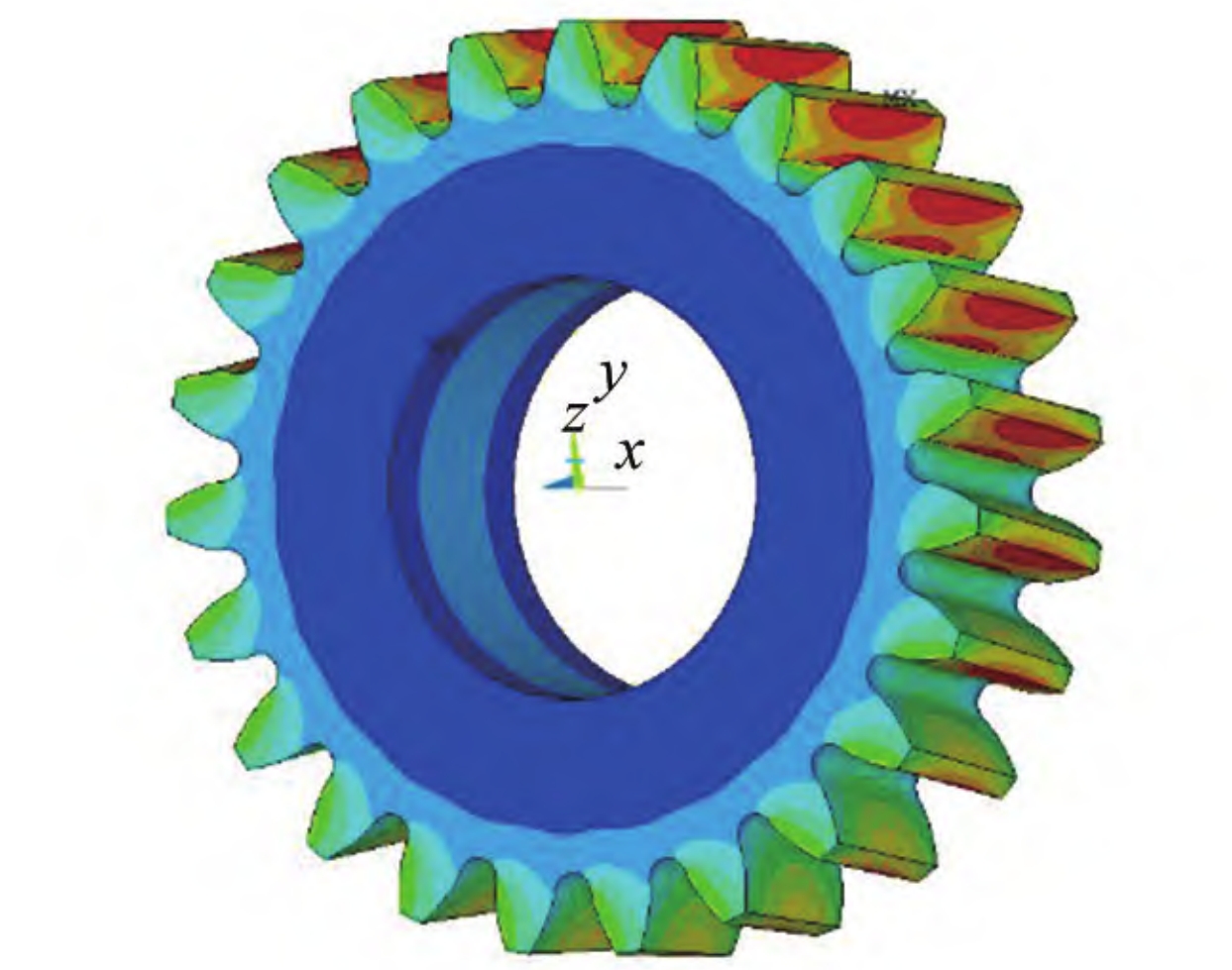
Thermal Deformation Field
The thermal deformation field of the driving gear, obtained by applying the steady-state temperature field as a load and constraining the inner hole.
Deformation Distribution
- Maximum Deformation: Occurs at the tooth tips, with the least deformation observed at the hub. The maximum deformation region is located near the ends of the gear.
- In the Meshing Line Direction: The deformation is greater at the rear end than the front end, consistent with the temperature distribution.
Influence of Gear Models
To investigate the influence of different gear models on the accuracy of the results, single-tooth, three-tooth, five-tooth, and full-tooth models were analyzed.
Steady-State Temperature Field
The steady-state temperature fields for the different gear models. The temperature distributions are similar, with the highest temperatures ranging from 92.4708°C (single-tooth model) to 92.7150°C (five-tooth model).
The relative errors between the single-tooth, three-tooth, and five-tooth models and the full-tooth model are small, indicating that the single-tooth model can be used to accurately predict the steady-state temperature field with reduced computational cost.
Thermal Deformation Field
The thermal deformation fields for the different gear models. The deformation patterns differ significantly, particularly for the single-tooth model.
The single-tooth model exhibits the highest deformation at the tooth midsection, whereas the full-tooth model shows maximum deformation near the tooth tips. The errors in the deformation field predictions are substantial for the partial-tooth models, highlighting the need for the full-tooth model for accurate thermal deformation analysis.
Conclusion
This study investigated the steady-state temperature field and thermal deformation field of electric drive helical gears using finite element analysis. The following key findings were obtained:
- Temperature Field Distribution: The meshing surface exhibits the highest temperature, with a gradient decreasing towards the hub. The temperature is highest in the double-tooth meshing regions and exhibits an “M”-shaped distribution in the tooth height direction. The temperature is asymmetric in the tooth width direction.
- Thermal Deformation: The maximum thermal deformation occurs at the tooth tips, with minimal deformation at the hub. The maximum deformation region is located near the ends of the gear. In the meshing line direction, the deformation is greater at the rear end than the front end.
- Model Influence: The single-tooth model can accurately predict the steady-state temperature field with reduced computational cost but is inadequate for thermal deformation analysis. The full-tooth model is necessary for accurate predictions of both the temperature and deformation fields.