
According to the definition of gear stiffness:
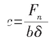
It can be seen that the deformation of gear teeth has a linear relationship with the stiffness. Therefore, the time-varying meshing stiffness and the load distribution between teeth can be used to calculate the gear deformation.
The accurate calculation of gear comprehensive meshing stiffness is an important foundation and primary premise for gear tooth modification, dynamic characteristic simulation, mechanical fault diagnosis and maintenance, and gear parameter optimization design. In gear modification, meshing stiffness runs through the whole calculation process. In general, the coincidence degree of gears is not an integer. The logarithm of teeth participating in the meshing is also constantly changing during the meshing process, and it changes periodically with time, which results in the elastic deformation of gear teeth from the root to the top of the tooth. Similar to the law of the logarithm change of the meshing teeth, the elastic deformation of the teeth is also a function of the time change, and it can also be characterized as a function of the load angle change.
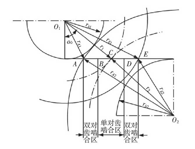
For spur gears, the number of teeth in mesh with time is related to the end face coincidence ε α. For a gear pair whose end face coincides between (1-2), the meshing area can be divided into single tooth meshing area and double tooth meshing area. In the double tooth meshing area, because two pairs of teeth mesh at the same time, the comprehensive stiffness is the sum of the two pairs of teeth. Due to the alternate operation of single and double pairs of teeth, the comprehensive meshing stiffness of gears is also a periodic function of the change of time or load angle. In the figure: B, D – dividing point of single and double tooth meshing area; a, e – Top meshing point of large and small gears; C – node, as shown in Figure 1.
At present, there are three kinds of methods to calculate the meshing stiffness of gears: material mechanics method, elastic mechanics method and numerical analysis method. But in recent years, with the development of computer technology, the finite element method is more and more frequently used in the study of gear dynamics by many experts and scholars. From the theoretical point of view, the material mechanics method is still the most widely used method, and its outstanding representative: Ishikawa formula is also widely used in the calculation of the meshing stiffness of spur gears.
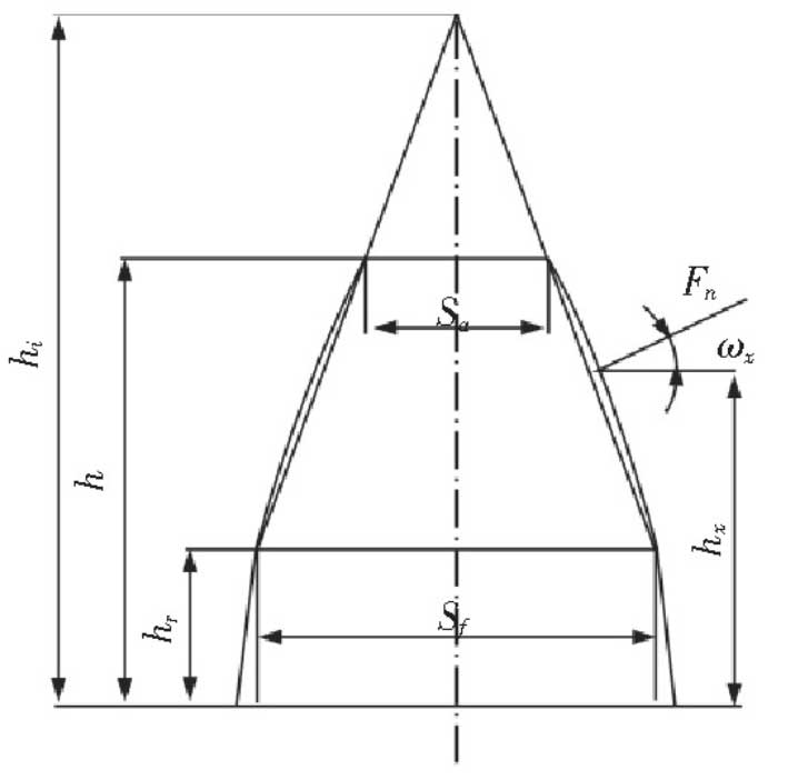
The meshing stiffness of spur gear can be calculated according to Ishikawa formula. Due to the complexity of gear tooth shape, Ishikawa method simplifies it to simply supported beam, that is, a trapezoid plus rectangular model combination, as shown in Figure 2. Thus, the deformation of each part of the gear tooth can be obtained.
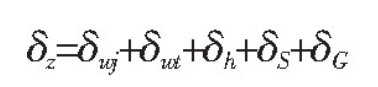
The deformation of gear teeth mainly includes the bending deformation, shear deformation, the deformation caused by the elastic inclination of the matrix and the contact deformation of gears in the rectangular part and trapezoid part of the equivalent tooth profile, which can be regarded as the synthesis of these deformations. The bending deformation of the rectangular part is represented by the symbol δ WJ, the bending deformation of the trapezoid part is δ WT, the contact deformation is represented by δ h, the shear deformation is δ s, the deformation caused by the elastic inclination of the matrix is δ g, the total deformation is δ Z, and the units of deformation in the formula are μ M.
The bending deformation formula of rectangular and trapezoid parts can be deduced according to the moment formula combined with Karnaugh’s theorem, as follows:
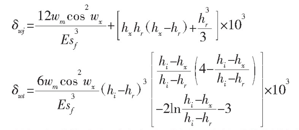
The shear deformation formula can also be deduced based on the virtual work principle:
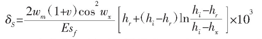
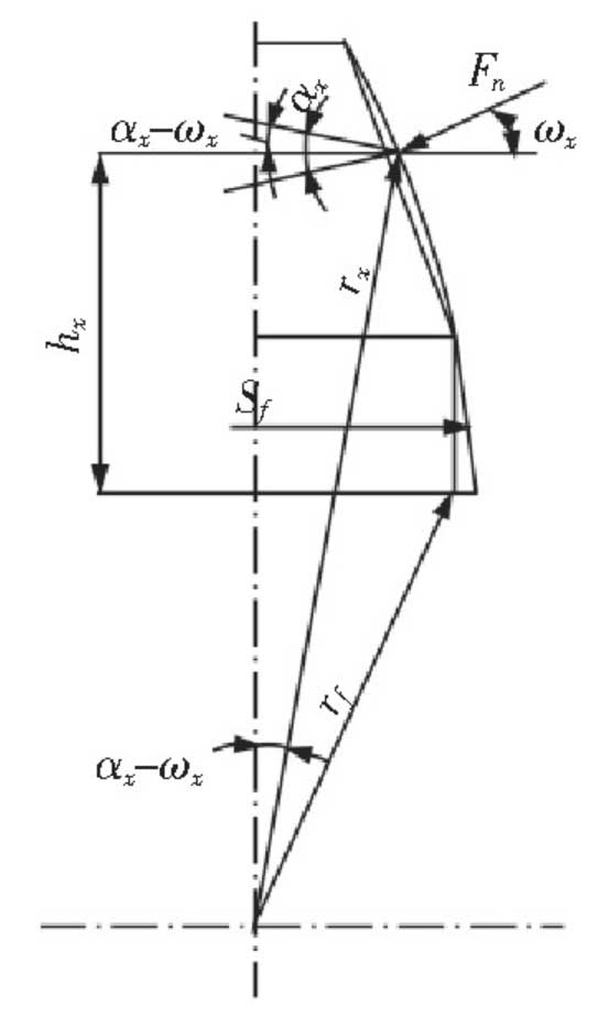
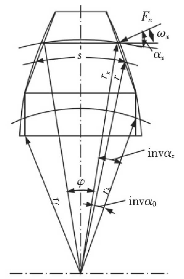
Where: WM is the average linear load in the direction of tooth width; V is Poisson’s ratio; E is the elastic modulus of gear material; h is the height of gear tooth; HX is the height of engagement point, as shown in Figure 3. Wx – load action angle, mathematical model, as shown in Figure 4. The specific formula is as follows:
For the contact deformation of gears, the radius of curvature at the contact line of driving and driven gears should be considered, and the radius of curvature can be calculated according to Hertz formula. When a pair of involute gears are engaged, the contact of the tooth profile can be regarded as the contact of two cylinders with the curvature radius of the two tooth profiles at the contact point, as shown in Figure 5.
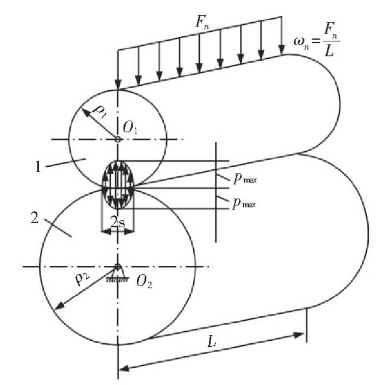
It is assumed that the contact line width is 2S, and the radius of curvature at the contact line of the main and driven gears is ρ 1 and ρ 2, respectively
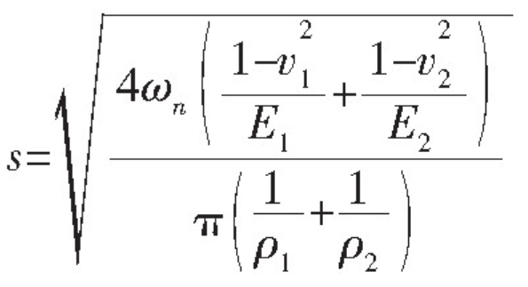
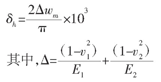
Thus, the formula of contact deformation can be deduced
The deformation caused by the elastic inclination of the matrix can be derived from the analysis of the bending moment and the plane elasticity of the semi infinite elastic body in reference.
For the helical cylindrical gear, the meshing process starts from one end of the gear, then gradually extends to the entire tooth surface, and finally exits from the other end of the gear. This gradual change directly determines that the helical gear is no longer abrupt in the N and N + 1 pairs of teeth meshing alternation, and also determines that the time-varying meshing stiffness of the helical gear is substantially different from that of the spur gear When the spur gears are meshed alternately, there will be a step change, while the helical gears will float up and down around a small range of values. According to the meshing principle of helical gear, the effective contact line length of single pair of teeth increases first, then maintains for a period of time, and finally gradually reduces to 0 until it exits the meshing.
Many experts and scholars at home and abroad have done a lot of research on the method of solving the mesh stiffness of helical gears. However, due to the complexity of helical gear structure, including the existence of end face and normal surface, there is no accurate and unified calculation formula or standard at present. There are two main methods: (1) first get the local mesh stiffness according to the formula, and then get the final mesh stiffness curve through the sum of discrete points (2) fit by Fourier series.
Local engagement stiffness:
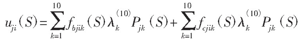
In the formula: fbjik (s) – bending deformation influence coefficient; λ (10) k – Gauss quadrature formula coefficient; fcjik (s) – contact deformation influence coefficient; PJK (s) – the j-th pair of teeth act on the engagement position s and act on any k point of the contact line.
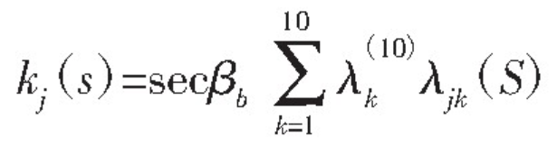
Meshing stiffness of single pair of teeth:
Total engagement stiffness:

However, according to the change curve of helical gear mesh stiffness, the curve can be fitted by Fourier series [3]. Generally, the peak value and average value of stiffness are calculated first, and then the stiffness curve is approximated as periodic function according to the meshing frequency. Omitting the high-order term is the fitted stiffness curve: n
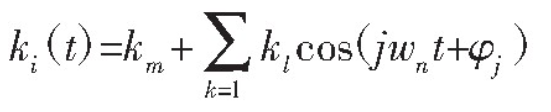
In the formula: km – average stiffness; KL – peak stiffness; φ J – corresponding phase angle; wn – circumferential frequency of gear tooth engagement, the specific calculation formula is as follows:
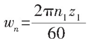
Where: N1 – driving wheel speed; Z1 – driving gear number.