According to the forming principle of the circular arc tooth line cylindrical gear, in theory, the circular arc tooth line cylindrical gear can finish the cutting of the three-dimensional digital model by the mutual movement of the gear blank and the circular arc tooth line basic rack. When cutting the standard circular arc tooth line cylindrical gear, the gear blank graduation circle shall be tangent to the basic rack graduation line of the circular arc tooth line, and the motion relationship shall meet the following formula:
S= theta * R (1)
Where: θ – gear rotation angle; R – gear blank pitch circle radius; s – Basic rack displacement of arc tooth line.
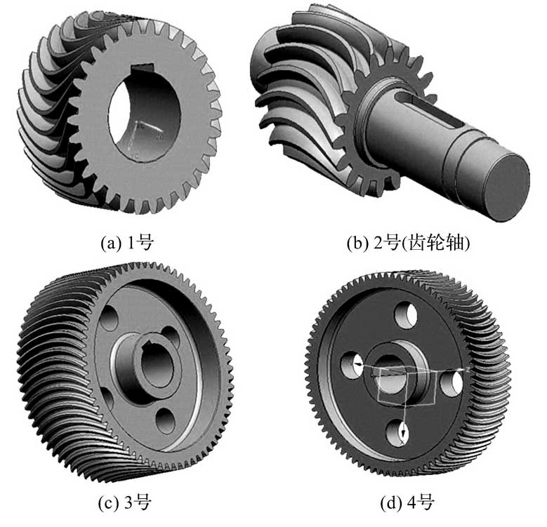
Based on the above methods, the author uses UG / open grip language to carry out secondary development and programming in the modeling environment of UG. In the modeling environment of UG parts, the program is called to input the module, the number of teeth and the radius of tooth line (r = 500 mm) of the gear to be cut, and to cut the required gear. According to the gear parameters of zqa50 involute cylindrical gear reducer, the cutting of No.1-4 gear of circular arc cylindrical gear reducer is completed.
It can be seen from the observation of the tooth surface of the circular arc tooth line cylindrical gear that there are many machining “knife marks” on the tooth surface of the gear, which can not be directly used for the finite element analysis and need to be further processed.
Take the large gear of intermediate shaft as an example (the rest is not described in detail). The specific processing steps are as follows:
(1) The design feature cylinder surface is established on the end face of the gear, a certain tooth is selected, and the cylinder surface intersects with the tooth profile. After the tooth surface curve is obtained by the command of finding the intersection line, it is connected by the command of connection;
(2) In the first step, the middle section and the two ends of the tooth are selected to draw the tooth profile, and the tooth surface is obtained by the command of “through curve grid”;
(3) Sew the obtained tooth surface array. The solid model of the circular arc gear can be obtained by the difference between the designed characteristic cylinder (the radius is greater than the tooth top circle radius) and the sewn tooth surface, as shown in Figure 1.

Finally, the subsequent processing, such as shaft hole, keyway, chamfer and so on.
Other circular arc tooth line cylindrical gears are obtained according to the same method, as shown in Fig. 2.

For other parts of circular arc tooth line cylindrical gear reducer, such as box body, bearing cover, bearing, gasket, oil mark, peephole, oil retaining ring, connecting bolt, oil unloading screw, bearing cover screw, etc., 3D modeling shall be carried out according to design parameters, which will not be described here.
Furthermore, the assembly model of the circular arc tooth line cylindrical gear reducer is further established in this paper, which provides technical support for the subsequent finite element simulation of contact performance.
