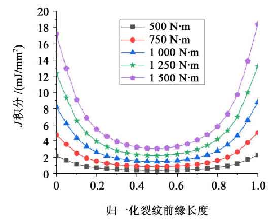
After the three-dimensional model of the gear is established, the material used in gear simulation is 17CrNiMo6, and then the helical gear pair model with semi elliptical initial crack is created. Taking the radius of the major and minor axes of the semi elliptical as 1 mm, the boundary conditions are imposed on the gear pair, and only the degree of freedom of the driving gear in the direction of rotation to be applied torque is retained, and the rest are constrained. The torque of 500 N · m, 750 n · m, 1 000 n · m, 1 250 n · m and 1 500 N · m was applied to the driving wheel respectively, and then the stress intensity factor and J-integral of the three-dimensional crack front were calculated. Figure 1 shows the curve distribution of three-dimensional stress intensity factors under different loads, and Figure 2 shows the numerical distribution of J-integral under different loads on the driving wheel. In order to explore the variables of initial 3D crack parameters simply and accurately, the crack leading edge length is normalized.
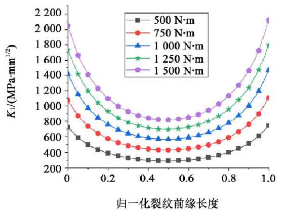
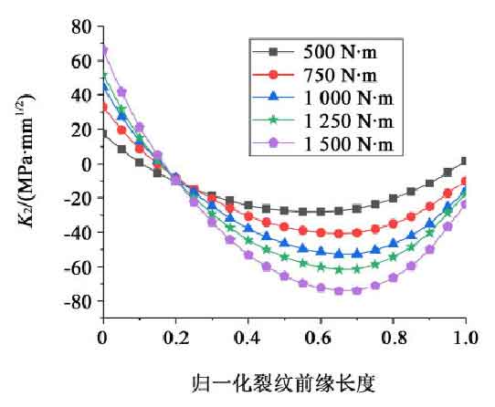
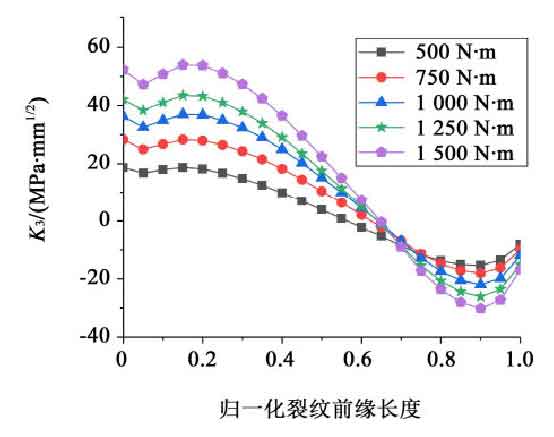
As shown in Fig. 1 (a), with the increase of load, the crack leading edge K1 also increases, and the two sides of the curve become steeper and steeper, while maintaining the law of high, medium and low on both sides. It can be seen from Fig. 1 (b) and Fig. 1 (c) that with the increase of load, the stress intensity factors of K2 and K3 at both ends of the crack leading edge are increasing, and the curves still keep the same change law. It can be seen from the three figures in Fig. 2 that with the increase of load, the three stress intensity factors are increasing, but the stress intensity factors of K2 and K3 at the crack front are far less than those at the crack front K1 stress intensity factor, K1 stress intensity factor is dominant; with the increase of load, J-integral also increases, and with the increase of load, both sides of the curve become steeper and steeper; at the same time, the law of high middle and low middle on both sides is maintained. It can be seen from Fig. 1 (a) and Fig. 2 that the change law of J-integral and crack front K1 is basically the same.