
As shown in the figure, the structure diagram of the pre forging die for the half shaft gear is given. The tooth die of the pre forging die for the half shaft gear is the upper die, the contact time between the tooth die and the high-temperature blank is short, and the temperature rise of the die is small, which is conducive to improving the service life of the tooth die. In addition, it can make it difficult for oxides to accumulate in the tooth model cavity: the half shaft female die is the lower die, and the unilateral clearance between the half shaft gear blank and the concave model cavity is 1.0mm, The semi axle gear blank can be directly positioned and pre forged by using the combination of the semi axle gear blank diameter and the concave mold cavity. The semi axle gear blank has a large deformation. In order to ensure the accurate guidance of the upper and lower dies, the dies are guided by guide posts and guide sleeves.
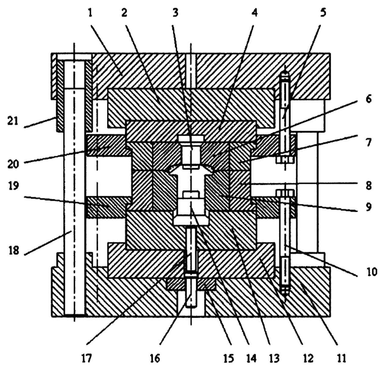
The upper base plate 2 and the lower base plate 12 are respectively fixed on the upper template 1 and the lower template 11 with screws. In order to make the figure clear, the screws connecting the upper and lower base plates and the upper and lower templates are not drawn as shown in the figure. The tooth mold 6 and the tooth mold sleeve 7 are prestressed, and the screw 5 uses the upper pressing ring 20 to fix the tooth mold sleeve on the upper template. The half shaft die 9 and the half shaft die sleeve 8 are prestressed, and the screw 10 uses the lower pressing ring 19 to fix the half shaft die sleeve on the lower formwork.
The forging of the axle shaft gear starts, the upper die goes down, the guide post is first introduced into the guide sleeve, and then the upper die contacts with the blank, and the forging and forming of the axle shaft gear blank begins: after the forging of the axle shaft gear, the upper die goes up, the axle shaft gear forging is left in the axle shaft female die, and the forging is ejected by the lower ejector of the friction press.