1. Single nail clamping structure
The contour spiral bevel gear milling cutter head for machining contour spiral bevel gears is a kind of pointed tooth milling cutter head. Before cutting, the milling cutter bar needs to be installed into the cutter slot of the contour spiral bevel gear milling cutter head and fixed with clamping screws. Because the machining of contour spiral bevel gear requires high precision, it is necessary to adjust the position of the tool tip on the contour spiral bevel gear milling cutter disc to adapt to the tooth surface contact in the cutting process. This process is called tool adjustment. The accuracy of adjustment is related to the machining accuracy, so it is very important to improve the clamping structure.
The previously used clamping structure of contour spiral bevel gear milling cutter bar has only a single clamping screw, such as the single screw clamping structure shown in Figure 1.
2. Double nail clamping structure
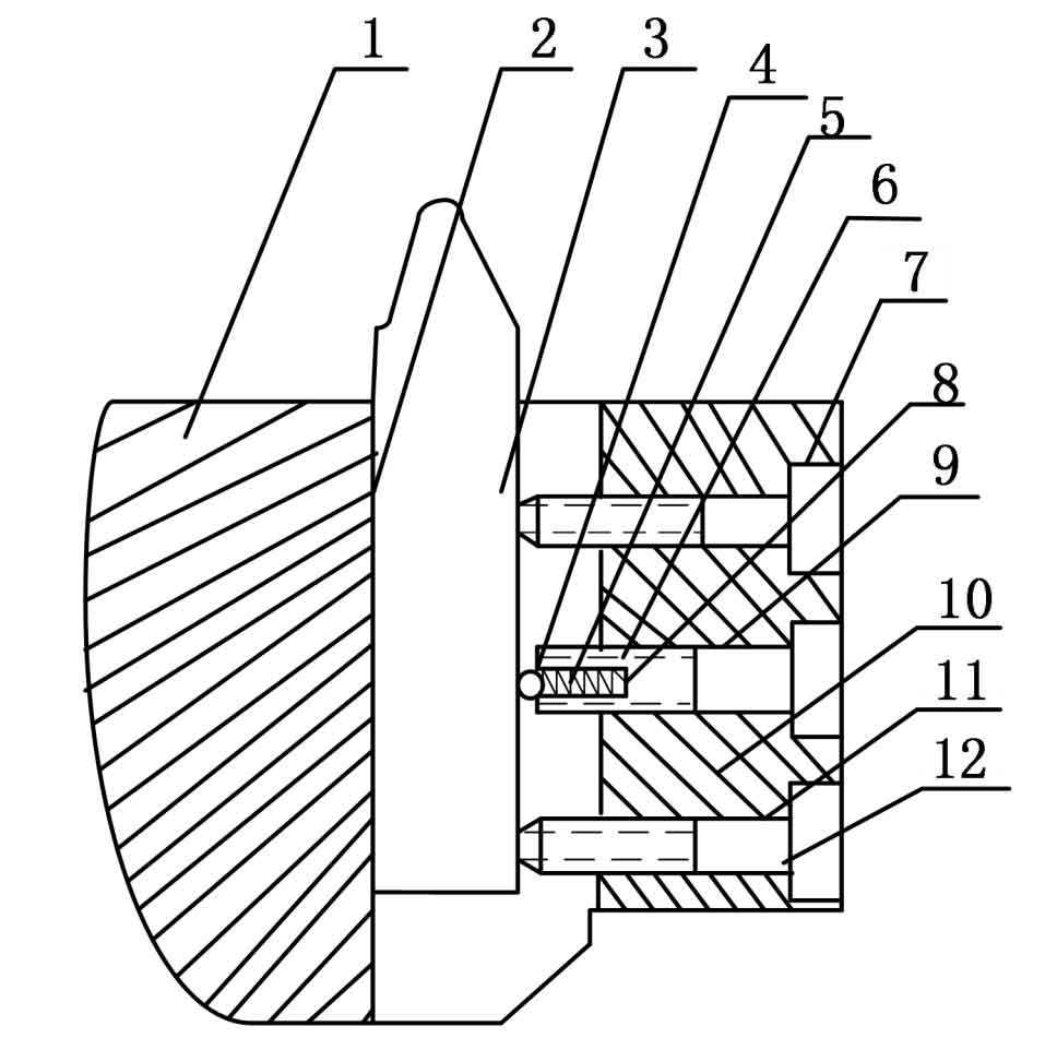
As shown in Figure 2, the double screw clamping structure and the improved double screw clamping structure are mainly used to process gears with small modulus. A pre tightening screw is set. The pre tightening screw is provided with a pre tightening cavity and connected with the pre tightening spring. When the tool adjustment is carried out for the milling cutter bar of equal high tooth spiral bevel gear, the elastic force of the spring on the pre tightening screw will have a certain binding force on the milling cutter bar, and the milling cutter bar of equal high tooth spiral bevel gear will not change with its own gravity, The adjustment is easy to operate. After the adjustment is completed, tighten the locking screw firmly to fix the position of the milling cutter bar of the equal height spiral bevel gear. By setting pre tightening screws, the success rate of tool adjustment is improved.
3. New three nail clamping structure
The new three pin clamping structure, as shown in Figure 3, is mainly used to process gears with large modulus. The overall weight of the cemented carbide cutter required is relatively large. When using the tool setting instrument, it is not easy to adjust the cutter bar. Each equal height spiral bevel gear milling cutter bar needs to maintain a relatively accurate position and keep the adjustment error at 2 μ M to ensure that the fixed contour spiral bevel gear milling cutter bar meets the standard. Readjust those that do not meet the standard until they meet the requirements.

By setting the pre tightening screw hole and locking screw hole on the equal height spiral bevel gear milling cutter head, the pre tightening screw is set in the pre tightening screw hole, and the locking screw is set in the locking screw hole. By contacting the pre tightening steel ball in the pre tightening screw with the blade point through the pre tightening spring, and cooperating with the locking screw to contact the blade surface at the same time, before tightening the locking screw with the equal height spiral bevel gear milling blade, The pre tightening steel ball at the bottom of the pre tightening screw transmits the binding force to fix the contour spiral bevel gear milling cutter bar, so that the up and down movement of the contour spiral bevel gear milling cutter bar can be prevented when the locking screw is clamped, and then the contour spiral bevel gear milling cutter bar can be firmly locked with the locking screw, which will produce greater clamping force to ensure the position of the contour spiral bevel gear milling cutter bar in the whole cutting process, And ensure the cutting accuracy of the processed workpiece. Figure 4 shows the structure of pre tightening screw.


