
0 Introduction
The transmission error of the gear bearing transmission is an important index to evaluate the dynamic meshing performance of the gear, and the smaller the fluctuation amplitude of the bearing transmission error, the smaller the gear vibration. With the increase of gear speed, the gear is load-bearing
The requirements for the amplitude of error fluctuations are getting higher and higher. In recent years, scholars at home and abroad have carried out a lot of research on the transmission error of gear bearing. In 2005, Litvin et al. proposed an improved surface topology for linear contact involute helical gears to reduce gear bearing transmission errors. Fang Zongde et al. optimized the bearing transmission error of high coincidence spiral bevel gear. Sun Yuehai et al. deduced the expression of the relationship between the static bearing transmission error of the modified spur gear and the comprehensive modification parameters of the gear pair under constant load. Pears et al. proposed a predictive tooth The method of wheel bearing transmission error and the importance of considering the influence of other components in the gearbox is noted. Korta et al. used the finite element method to study the static load transmission of a pair of spur cylindrical gears by the lightweight gear body Effect of dynamic error. Benatar et al. studied the effect of helical gear modification on their load-bearing transmission error. Park studied the tooth surface friction and load-bearing transmission error caused by sliding friction of spur gears under quasi-static conditions Difference. Bruyere et al. deduced the optimal combination of tooth profile and tooth crest for spur and helical gears, so as to minimize the time-varying amplitude of the transmission error. Zhang Xijin et al. proposed a topological modification method for arc modification and spiral drum modification in the direction of helical gear tooth profile, and analyzed the transmission error of modified gear. Liu Xuan et al. proposed a herringbone gear composite modification design method to reduce the amplitude of the load transmission error Tooth surface flash temperature. To sum up, it can be seen that the current gear bearing transmission error and the corresponding repair A lot of research results have been made in the shape design, but there is little analysis of internal mesh spur gears. Internal meshing drives are generally used for planetary drives, usually in the form of short tooth heights. Therefore, this paper mainly discusses the modification method of internal meshing short-tooth spur gears. Firstly, the influence of modification parameters on the amplitude of bearing transmission error was analyzed by Romax software. In order to obtain a better modification effect, the modification optimization design method was further studied. Finally, it is carried out on the Romax software platform Comparative analysis of modification optimization. This work provides a reference for improving the dynamic meshing performance of internally meshing short-tooth high-spur gears.
1 Modeling of internally meshing short-toothed spur gears
Gear modeling is performed in the Romax software, and the gear set type is designed as a spur gear, and the gears are defined using parameters such as pressure angle, modulus, displacement factor, tooth width, tooth top height factor, and root height factor. The parameters of the internal gear pair studied in this paper are shown in Table 1. For the internal gear pair, the small wheel adopts the solid type, and the large wheel needs to consider the thickness of the rim. The formula for calculating the thickness of the rim of the large wheel is here The thickness of the edge is 16 mm.
δ0 = (2.5 ∼ 4)m,m≥8
Table 1 Parameters of internal meshing spur gear pairs
| 项目 | 小轮 | 大轮 |
| 齿数 | 53 | 160 |
| 模数/mm | 4.0 | 4.0 |
| 压力角(/ °) | 20 | 20 |
| 齿高系数 | 0.8 | 0.8 |
| 顶隙系数 | 0.3 | 0.3 |
| 齿宽/mm | 212 | 212 |
| 输入功率/kW | 600 | 600 |
| 小轮转速(/ r/min) | 1000 | 1000 |
2 Spur gear transmission modification method
2.1 Tooth profile modification
The gear profile modification parameters include the amount and length of tooth top and tooth root, and the coordinates of the conventional tooth profile modification diagram are represented in the direction of the meshing line, and the determination of the tooth profile modification parameters is cumbersome. In order to facilitate the modification process, the tooth profile modification diagram represented along the tooth height direction is used in this article, as shown in Figure 1. The tooth top and root parts can be parabolic or straight. In Figure 1, y1 is the maximum amount of modification at the top of the tooth and Y2 is the tooth The length of tooth top modification in the high direction, Y3 is the maximum modification amount of the tooth root, and Y4 is the modification length of the tooth root in the high direction of the tooth. In addition, considering the convenience of processing, the method of small wheel modification and large wheel non-modification is adopted. In order to analyze the influence of tooth profile modification parameters on the bearing transmission error,First of all, it is necessary to determine the range of variation of the modification parameters. The maximum modification amount of tooth top and tooth root adopts 5 values: 0. 010 mm、0. 015 mm、020 mm、0. 025 mm and 0. 030 mm。
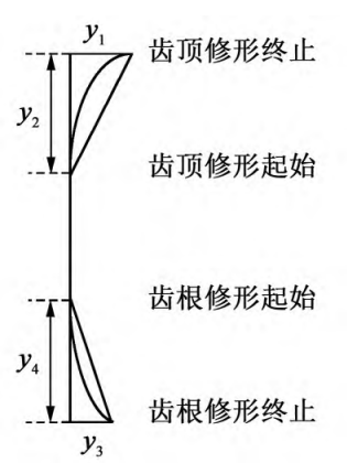
Fig.1. Tooth profile modification
2.2 Spiral shaping
There are two types of spiral modification of small wheels: end inverted slope and drum modification. In this article, the two modification methods are compared and analyzed, as shown in Figure 2. In Figure 2, y5 is the maximum helix trimming amount. In Fig. 2(a), Y6 is the length of the spiral inverted slope. The inverted slope of the shape curve is a straight line, and the drum shape is a parabola. For inverted slope modification, the maximum modification amount is generally 13~35 μm, and the modification length is 0. 25b, b is the tooth width. For drum trimming, high-precision, high-reliability gears, the amount of drum trimming is 10~25 μm, plus a manufacturing error of 5 μm.Similarly, in order to analyze the influence of helix modification on the bearing transmission error, the maximum spiral modification amount y5 adopts five values: 0. 010 mm、 0. 015 mm、 0. 020 mm、 0. 025 mm and 0. 030 mm。 When analyzing the influence of profile modification parameters, helix modification Drum shape modification is adopted, and the modification parameters are fixed; When analyzing the influence of spiral modification parameters, the spiral modification was carried out in two forms: end inverted slope and drum modification.
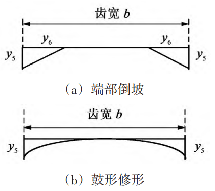
Fig.2. Gear helix line modification diagram
3 Internal mesh spur gear sub-modification analysis
3.1 The influence of tooth profile modification parameters on the bearing transmission error
In order to compare and analyze the influence of tooth surface modification on the load-bearing transmission error, the non-modification standard tooth surface load-bearing transmission error was first simulated by Romax software, as shown in Figure 3. In Figure 3, the load transmission error
The amplitude of the difference is 6. 69 μm。In order to analyze the influence of the modification parameters of each tooth profile on the bearing transmission error, the helix was modified in a drum shape, and the drum shape modification amount y5 was kept at 0. 020 mm, the tooth profile modification parameters are the following two cases:
(1) The maximum modification amount of the tooth top changes, and the other modification parameters remain unchanged, y2=1. 0Ld mm、y3=0. 020 mm、y4=1. 0Lg mm。
(2) The maximum modification amount of the tooth root changes, and the other modification parameters remain unchanged.y1=0. 020 mm、y2=1. 0Ld、y4=1. 0Lg mm。 In the analysis of the above modification parameters, the length of the tooth top and tooth root are taken as the length of the double tooth meshing zone, and Ld represents the length of the tooth top and Lg Root trimmed length. The analysis results of the first case are shown in Figure 4, with the increase of the maximum modification amount of the tooth top, the amplitude of the bearing transmission error fluctuation first decreases and then increases, and the best effect can be achieved by optimizing the maximum modification amount of the tooth top. The analysis results of the second case are shown in Fig. 5, for parabolic modification, with the increase of the maximum modification amount of the tooth root, the amplitude of the bearing transmission error decreases. But for straight line modification, the transmission error is loaded
The amplitude of the fluctuation first decreases and then increases.
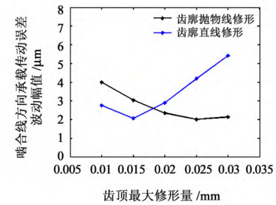
Fig.4. Effect of the maximum amount of modification at the top of the tooth
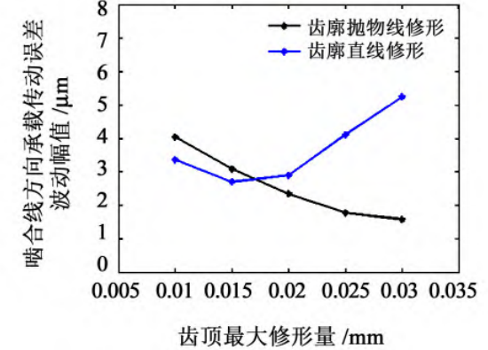
Fig.5. Effect of the maximum amount of tooth root modification
3.2 The influence of spiral modification parameters on the bearing transmission error
As mentioned above, when analyzing the influence of spiral modification parameters, the spiral modification is compared in two forms: end inverted slope and drum modification. The maximum modification amount of the helix changes, and the other modification parameters remain unchanged, y1=
020 mm、 y2=1. 0Ld、 y3=0. 020 mm、 y4=1. 0Lg、 y6=0. 25b。 The results of the analysis are shown in Figure 6, with the maximum amount of modification of the helix As the increase increases, the amplitude of the bearing transmission error becomes larger, which is caused by the decrease of tooth stiffness with the increase of the amount of modification. In addition, drum modification is better than end slope reversal.In addition, it can be seen from the comparison of Figure 6 that reasonable modification can effectively reduce the fluctuation amplitude of bearing transmission error.
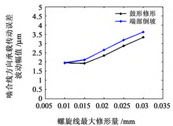
Fig.6. Effect of the maximum modification amount of the helix
4 Optimization design of modification parameters
Due to the fact that tooth profile parabolic modification and spiral drum modification are widely used in engineering, in order to obtain better modification results, this paper studies the modification parameters of tooth profile parabolic modification and spiral drum modification The design method minimizes the fluctuation amplitude of the bearing transmission error. In this paper, the Loaded Tooth Contact Analysis (LTCA) method is used to obtain the load-bearing transmission error expressed in the form of rotation angle. Similarly, the small wheel is used to trim the shape and the large wheel is not trimmed
formula, only optimize the modification parameters of the small wheel; In order to obtain better optimization results, the maximum modification amount of tooth profile, modification length and maximum modification of spiral were optimized.The particle swarm optimization algorithm (Particle Swarm Opti⁃mization (PSO) is a kind of stochastic optimization technology based on swarm intelligence, compared with genetic algorithms, both are based on swarm iterative search, but PSO algorithm does not have crossover and mutation operators, and searches for the optimal solution through cooperation between individuals, which makes use of the idea of information sharing in biological groups. PSO algorithms are easy to implement and are suitable for engineering applications. The modification optimization parameters are Y1, Y2, Y3, Y4, and Y5, and the particles are defined is Y=[y1 y2 y3 y4 y5]. The objective function f is the bearing transmission error The fluctuation amplitude is calculated using LTCA. The particle swarm optimization algorithm consists of five steps: (1) random initialization of particles in the particle swarm; (2) calculate the fitness (objective function value) of each particle; (3) calculate the optimal position experienced by the particle; (4) the evolution of particles; (5) judging the end condition (evolution to a preset algebra,Otherwise, go back and continue).
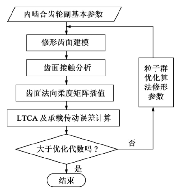
Figure 7 Modification and optimization process
The optimization result is: y1=28. 392 μm、y2=2. 139 588 mm、y3=28. 91 μm、y4=1. 672 763 mm、y5=13. 516 μm。Romax software is used to recommend and optimize the design method. In order to compare and analyze, the results of the modification optimization in this paper and the results of the Romax recommended modification and Romax optimization were simulated and analyzed in the Romax software platform. Romax recommends that the modification method is the one-way straight line modification method of the tooth profile, and the spiral line is not modified without considering the installation error, and the modification parameters are y1=16. 08 μm、y2=1. 28 mm、y3=16. 08 μm and
y4=1. 08 mm, the modification effect is shown in Figure 8, and the fluctuation amplitude of the bearing transmission error is 6. 45 μm。 In the Romax optimized modification method, both the tooth profile and the spiral are polished Object reshaping. Romax optimizes the use of genetic algorithms in the modification of the genetic algorithm, in conjunction with the present Under the same optimization parameters of the proposed optimization method, the Romax optimization modification results are as follows y1=16. 98 μm、y2=2. 475 512 mm、y3=21. 76 μm、y4=2. 024 798 5 mm and y5=10. 03 μm。 The modification effect is shown in Figure 9, and the amplitude of the bearing transmission error fluctuation is 3. 10 μm。 Of course, excellent The effect is related to the optimization parameters, etc.
As shown in Figure 10, the tooth profile and helix are both parabolic shaped, and the amplitude of the transmission error wave is 2. 86 μm。 The comparison of the modification effect is shown in Table 2. As can be seen from Table 2, the optimized modification design in this paper is better than that of Romax recommended modification and Romax optimized modification.

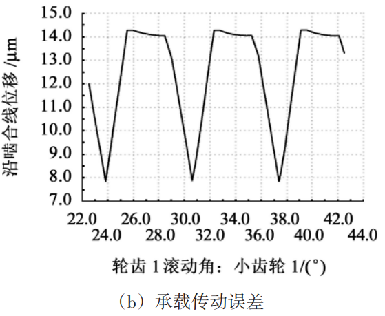
Fig.8 Romax recommended revision analysis
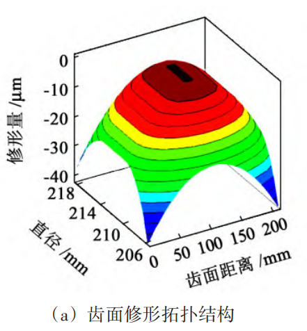
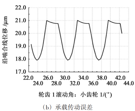
Fig.9 Romax optimization and modification analysis
5 Conclusion
The Romax software was used to establish the model of the internal meshing short tooth high spur gear, and the influence of the tooth profile and spiral modification parameters of the internal meshing short tooth high spur gear on the bearing transmission error was analyzed, and the optimization design method of the modification parameters was studied, and the following conclusions were obtained: (1) The influence of tooth top and tooth root modification on the fluctuation amplitude of bearing transmission error is nonlinear, because the tooth profile modification mode (straight line and parabolic modification) is different, and the influence of the maximum modification amount of tooth top and tooth root on the fluctuation amplitude of bearing transmission error is different.
(2) The spiral modification also has an effect on the bearing transmission error fluctuation amplitude of the internal meshing gear pair, and the drum modification effect is better than the reverse slope modification.
(3) Through comparative analysis, it is found that reasonable modification can effectively reduce the fluctuation amplitude of bearing transmission error.
(4) The optimization design method of modification parameters proposed in this paper can effectively reduce the bearing transmission error. The research results in this paper provide a basis for the modification design of internal meshing short tooth high spur gears with high transmission performance.
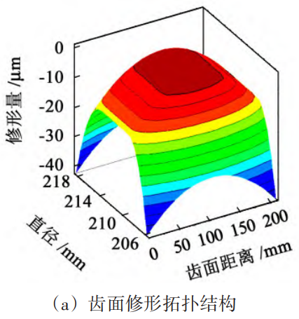
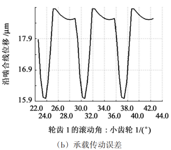
Fig.10 This paper optimizes the modification analysis