
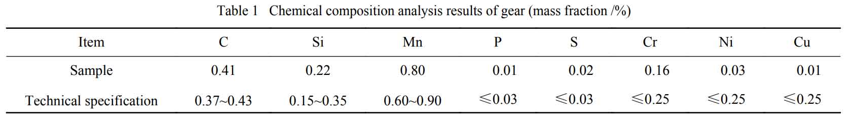
1. Chemical composition analysis
The chemical composition analysis results of steel gears are shown in Table 1, which meet the technical requirements.
2. Macro and micro morphology inspection
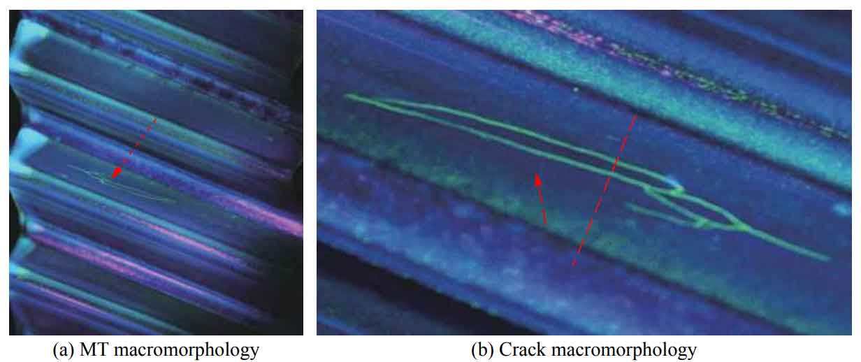
According to the magnetic particle testing of the steel gear, the morphology is shown in Fig. 1. The crack is located near the pitch circle (dotted arrow in Fig. 1), which is closed as a whole, crosses the grinding direction of the steel gear tooth surface at a small angle (< 15 °), and feels burr by hand. As for the crack on the tooth surface of steel gear, according to the T-shaped rule, it can be judged that the crack indicated by the dotted arrow in Figure 1 is formed first, and then it expands to the tooth top and tooth root to form secondary cracks, which is related to the bidirectional operation of steel gear during service.
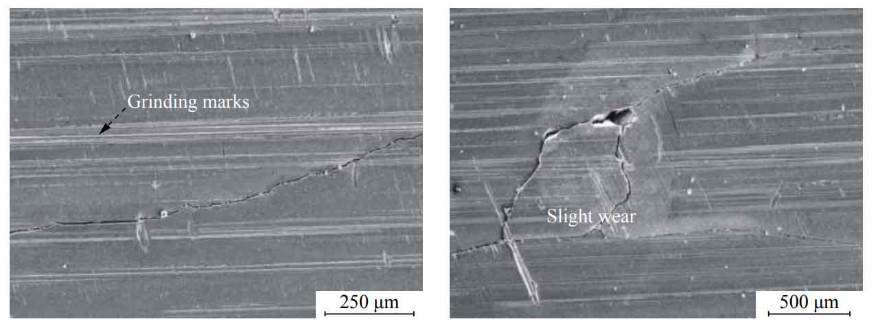
According to the microscopic appearance inspection, the grinding marks around the crack are clearly visible, and there are slight signs of wear along the meshing direction, which is the local wear caused by edge warping after cracking. There is no foreign matter filling in the crack cavity, and the coupling between both sides is good (Fig. 2).
In conclusion, according to the crack location and macro and micro morphology, it is speculated that the tooth surface crack of steel gear has the early characteristics of “peeling” caused by contact fatigue. The research shows that the spalling main crack usually occurs in the sub surface layer almost parallel to the tooth surface of the steel gear. As the crack extends upward to the tooth surface of the steel gear, the metal on the upper part will fall off and form corrosion pits. It is obvious that the crack of the steel gear in this study has cracked to the surface and has not fallen off.
3. Metallographic analysis
The following conclusions can be drawn by cutting samples along the red dotted line in Figure 1 for metallographic analysis:
1) According to the contact fatigue crack propagation characteristics, it can be inferred that the crack source is located at the red circle in Fig. 3a, which is about 0.4 mm away from the tooth surface of the steel gear. After the crack initiation, it expands along the direction of the red dotted arrow. It is worth mentioning that according to theoretical calculation, the maximum Hertz stress of steel gear is just 0.3 ~ 0.4 mm below the tooth surface of steel gear.
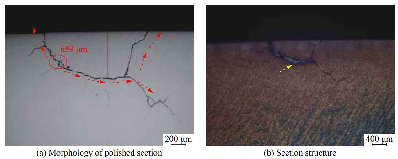
2) 4% (mass fraction) nitric acid ethanol was used to etch the test surface in Fig. 3a. It was found that the color within about 0.5 mm from the steel gear tooth surface was black, which was easier to etch and discolor than the sub surface layer (Fig. 3b). It was speculated that the steel gear tooth surface may have the phenomenon of “high temperature tempering”.
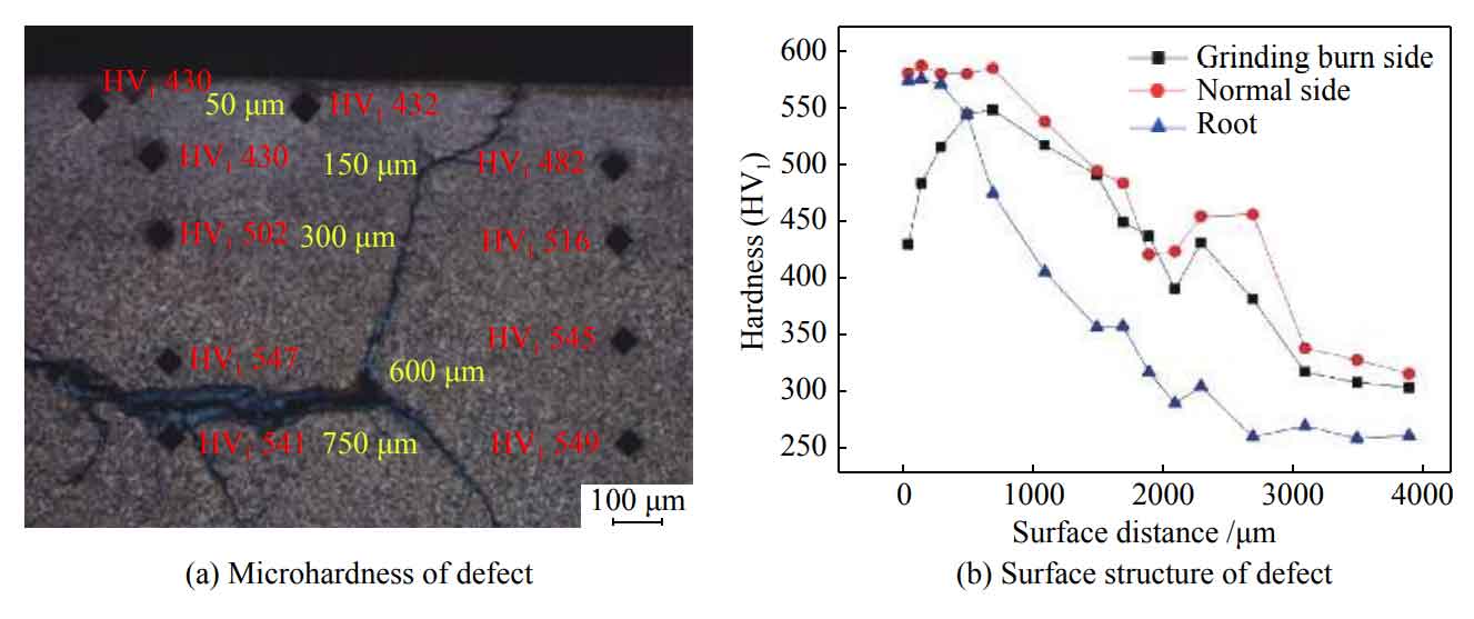
3) The microhardness test results are shown in Figure 4, 50 away from the surface μ The hardness at M is about HV1 420, which is about HV1 150 lower than the normal area. The total depth of “low hardness area” is 0.5 mm, which is consistent with the main crack propagation depth in Fig. 3a and the corrosion morphology in Fig. 3B.
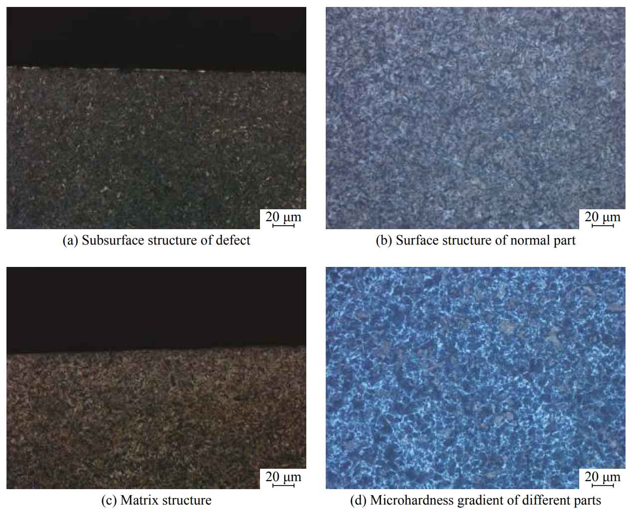
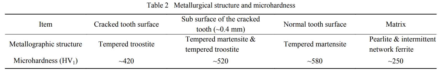
4) The microstructure of each part is shown in Fig. 5, and the microstructure and hardness are shown in Table 2. It is confirmed that there is tempering on the tooth surface of steel gear at the defect. The microstructure of normal steel gear tooth surface is evaluated as grade 4 according to JB / T 2008 metallographic inspection of induction quenching of steel parts.
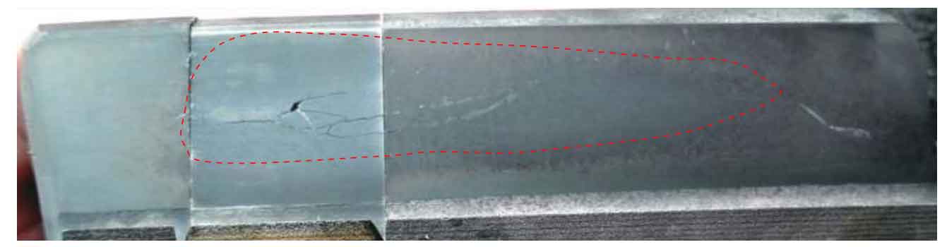
In addition, acid immersion corrosion inspection was carried out on the tooth surface of the defective steel gear. It can be seen in Figure 6 that the color of the red dotted line area is black, and the tempering discoloration is obvious, and the area is large, accounting for almost the whole working area of the tooth surface of the steel gear.
To sum up, there is a tempering layer with a depth of about 0.5 mm on the surface of the cracked wheel steel gear tooth. The contact fatigue crack originates at a distance of 0.4 mm from the gear surface, and the initiation position is just located in the transition area of the tempering burn layer and at the maximum Hertz stress.