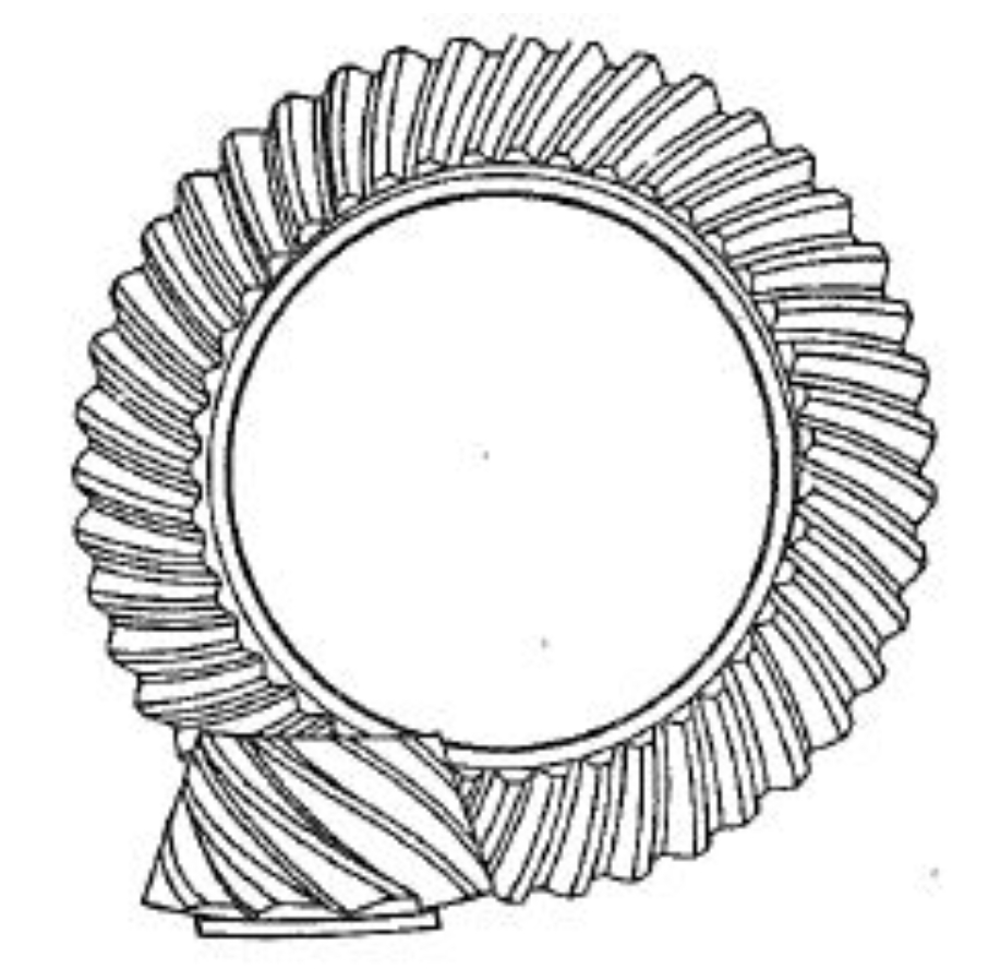
This study addresses the challenges in controlling meshing quality for high reduction hypoid gears (HRH) through advanced surface synthesis and modification techniques. A comprehensive mathematical framework is developed to optimize tooth contact patterns and dynamic performance.
1. Spatial Meshing Equation and Coordinate Transformation
The general meshing equation for crossed-axis gear transmission is established as:
$$f(u, v, \phi) = \mathbf{n} \cdot \mathbf{v}^{(12)} = 0$$
Where the velocity components in orthogonal directions are expressed as:
$$
\begin{cases}
U = n_x(E + z_2\cos\gamma) – n_z(y_2 – G) \\
V = n_z(x_2 – E) – n_x(z_2\sin\gamma + G) \\
W = n_y(x_2 – \frac{m_{21}}{\sin\gamma}n_zE)
\end{cases}
$$
2. Crowned Tool Surface Modification
The modified cutter profile with parabolic correction is defined by:
$$
\begin{cases}
w = 0.5a(u – u_0)^2 \\
\alpha_2(u) = \arctan(w’) + \alpha_0
\end{cases}
$$
Key tool modification parameters are summarized in Table 1.
| Parameter | Concave | Convex | Gear |
|---|---|---|---|
| Cutter radius (mm) | 77.725 | 72.644 | 37.3/38.9 |
| Pressure angle (°) | 20.0 | 28.0 | 21.0 |
| Radial setting (mm) | 52.086 | 51.678 | 53.151 |

3. Ease-off Topology Control
The ease-off gradient ellipse is formulated as:
$$
\frac{x^2}{a^2} + \frac{y^2}{b^2} = \frac{\delta^2}{4}
$$
With curvature correction parameters:
$$
\begin{cases}
k_a = \frac{8\delta}{a^2} \\
k_b = \frac{8\delta}{b^2}
\end{cases}
$$
4. Machine Setting Optimization
The numerical solution for machine settings is obtained through constrained optimization:
$$
\min \sum_{i=1}^{15} [\mathbf{r}_s^{(i)} – \mathbf{r}_1^{(i)}]^2 + [\mathbf{n}_s – \mathbf{n}_1]^2
$$
Key optimized parameters for hypoid gear generation include:
- Machine root angle: 10.991°
- Vertical offset: 39.884 mm
- Cradle ratio: 20.015
5. Contact Pattern Simulation
The ease-off topography (Figure 1) demonstrates effective contact pattern control with maximum deviation of 196 μm. Transmission error analysis reveals:
$$
\Delta\phi = \frac{1}{2\pi} \int_0^T \left(\frac{\omega_1}{\omega_2} – \frac{z_2}{z_1}\right) dt
$$
6. Dynamic Performance Validation
Vibration spectra show dominant meshing frequency components:
$$
A(f) = \sum_{n=1}^\infty C_n \delta(f – nf_m)
$$
Where the meshing frequency for 3:60 hypoid gear pair at 1410 rpm is:
$$
f_m = \frac{1410}{60} \times 3 = 70.5 \text{ Hz}
$$
7. Conclusion
The proposed surface synthesis method enables precise control of hypoid gear tooth contact characteristics, achieving:
- Contact ellipse ratio 1:2.4
- Transmission error < 1 arcmin
- Vibration acceleration < 3.11 m/s²
This methodology provides an effective solution for high-reduction hypoid gear design and manufacturing, particularly suitable for applications requiring high power density and silent operation.
