
1 Meshing stiffness excitation
Meshing stiffness is one of the important parameters of gear transmission system, taking the gear of uniform meshing transmission as an example, its meshing force is always along the direction of the meshing line, and the size of the meshing force does not change, because the change of the number of meshing gear teeth makes the meshing force from one pair of teeth to two pairs of teeth. whereas
The gear teeth are generally made of medium and high carbon steel materials, although the material itself is high The stiffness, but not the absolute rigid body material, under the action of the meshing force, a pair of gear tooth shape variable is greater than two pairs of gear tooth shape variable, this alternating deformation will cause the vibration of the gear, so the gear teeth in the meshing area will cause the vibration of the gear teeth due to the change of meshing log, and its vibration is called meshing stiffness excitation, which is an inherent property of the gear transmission system. Wheels in the actual meshing process The tooth will manifest as periodic minute vibrations. Gear meshing stiffness excitation mainly considers the influence of amplitude and vibration frequency on the gear transmission system, the influence of amplitude on the gear transmission system is manifested as a small amplitude of periodic vibration, the amplitude of gear meshing stiffness excitation can be regarded as the inherent additional load of the transmission system, and this inherent additional load has zero part of the transmission system The effect of the strength of the piece is very small, and the stress generated by the additional load is much lower than the allowable stress of the transmission system material; However, the influence of vibration frequency on the gear transmission system is manifested as a certain periodic vibration, which may cause huge damage to the transmission system, because a certain periodic vibration may trigger resonance to the transmission system components, and then make the transmission system components fail for a short time, as shown in Figure 1 due to the fracture caused by the local resonance of the gearbox of the high-speed train. In addition, the size of the meshing stiffness is not only affected by the load change, but also depends on the geometry, material properties, meshing method and other factors of the gear, which directly affects the gear transmission Dynamic characteristics and transmission accuracy of the system.
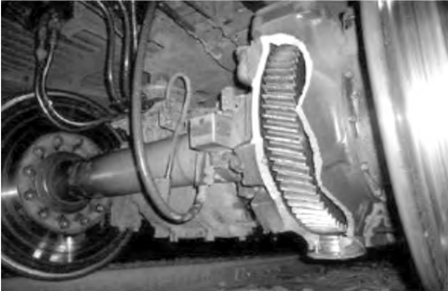
Figure 1 Local resonance fracture of the chamber
Taking the involute spur round external meshing gear as shown in Figure 2, for example, according to the gear coincidence calculation formula such as Equation 1, it can be seen that the coincidence of the involute spur circle external meshing gear is between 1-2, and the larger the coincidence value, the longer the meshing section of the double tooth meshing ratio. Figure 1 The coincidence degree of the gear meshing geometry is 1.3, through the Figure 1 gear meshing geometry, it is not difficult to find that there are three meshing segments, and the number of gear teeth meshing pairs in different meshing sections is different, from left to right, the gear teeth meshing of the DC section is a pair, the gear tooth meshing of the CB section is two pairs and the gear tooth meshing of the AB section is a pair, and the CB double tooth meshing accounts for 30% of the meshing area.
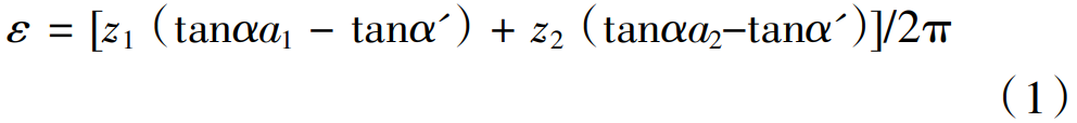
Formula: z1, z2 is the number of teeth; αa1, αa2 are the top of the tooth round pressure angle, α’ is the meshZygo.
The coincidence of the gear transmission will have an impact on the stability of the gear transmission system, and the higher the coincidence value, the transmission is about stable. The coincidence formula of spur cylindrical gear is an extreme value condition, the large value of the coincidence is 1.98, to further improve the coincidence degree need to make the gear into a helical gear, the meshing stiffness excitation of helical gears is smaller than that of spur gears. Therefore, time-varying stiffness excitation is one of the main factors to be considered in the dynamics of the gear drive system. The tooth contact during tooth meshing transitions from a single pair of teeth to two pairs of teeth and then to a single pair of teeth, as shown in Figure 2. Therefore, the load transmission is borne by a single pair of gears, overbearing to a double-tooth gear, and then to a single-tooth gear. The meshing stiffness of the gear is defined as the normal load required under the normal elastic deformation of the unit, so the comprehensive meshing stiffness k of the gear is shown in Equation (2).
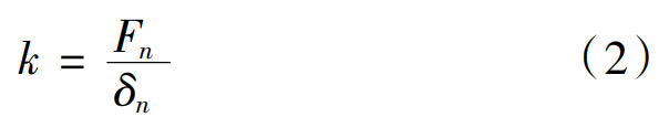
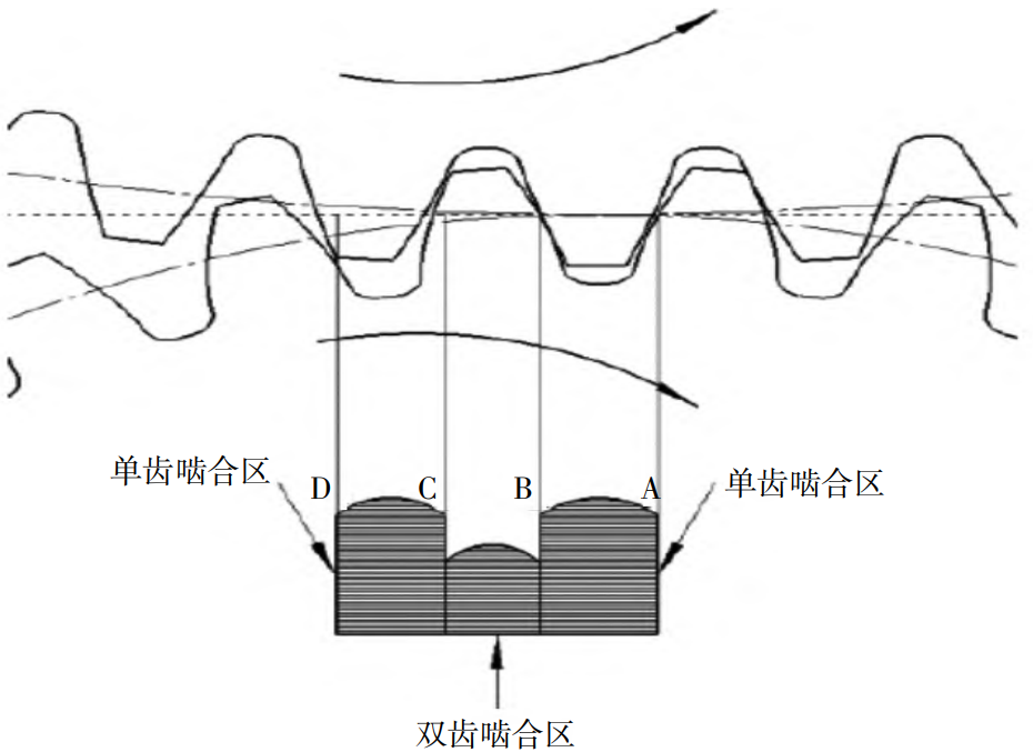
Figure 2 Gear meshing area
where : k is the comprehensive meshing stiffness of the gear, Fn is the normal contact force, and δn is Normal elastic deformation. However, Equation (2) can only react statically to the gear meshing stiffness, and cannot dynamically react to the change of gear meshing stiffness, as shown in Figure 2 gear meshing
Geometric model, knowing that the number of gear teeth pairs of gear meshing will produce alternating changes, so the meshing stiffness of the gear will also produce periodic row changes, and its gear meshing stiffness tooth formula (3) is expressed.
Where: k is the meshing stiffness, km is the average meshing stiffness, kα is the stiffness amplitude, and φ is the phase angle. The study of meshing stiffness mainly focuses on theoretical calculations and realities
There are two aspects of the measurement. The theoretical calculation mainly adopts numerical simulation methods such as finite element analysis and stone stiffness analysis. The Ishikawa stiffness method is the most widely used, which simplifies the meshed gear teeth into rectangular and trapezoidal combined cantilever beams, and obtains the gear meshing stiffness with the help of the material mechanics analysis method, but the Ishikawa stiffness formula method does not consider the deformation of the wheel body, and then Li Yapeng considers the deformation of the wheel body on the basis of the Ishikawa stiffness method, and obtains the improved Ishikawa rigid method. The finite element stiffness method is to mesh the gear solid structure into finite element bodies and fix the teeth
The wheel boundary conditions and applied load, the displacement of different meshing points of the gear teeth is obtained by the superposition operation of the unit body node, the gear tooth meshing stiffness is calculated by substituting the stiffness formula, and the meshing stiffness of the gear model is calculated by finite element, and the mesh quality directly affects the numerical accuracy of the meshing calculation stiffness. The experimental measurement mainly adopts laser interferometer, strain gauge and other test equipment, which can monitor and measure the deformation and stress distribution of the gear during meshing in real time. However, the current research on meshing stiffness still has some shortcomings. First of all, the existing theoretical calculation methods and experimental measurement methods have certain errors and limitations. It is not possible to fully accurately describe the amount of deformation and stress distribution when gears mesh. Secondly, the existing research mainly focuses on the meshing stiffness of single gears, and the meshing stiffness research of multi-gear systems is still relatively limited. Finally, the existing research mainly focuses on the study of static meshing stiffness, and the research on dynamic meshing stiffness is still relatively weak.
2 Meshing error excitation
Meshing error refers to the difference between the actual meshing position and the theoretical meshing position. Taking the gear diagram 3 of the uniform meshing transmission as an example, when the ideal active gear tooth profile A point and the passive wheel upper tooth profile B point mesh, the passive wheel can be driven by the active wheel at a constant speed, which is caused by the gear processing error and tooth pitch error Poor, tooth thickness error and other factors, so that the actual tooth profile on the passive wheel is at B, and the active gear tooth profile A must be rotated at an additional angle d so that the tooth profile A continues to move an additional distance TE along the meshing line, and the tooth profile A meshes with the actual tooth profile B of the passive wheel, and this distance TE is the transmission Error.
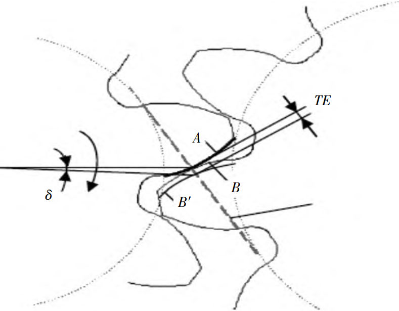
Figure 3 Gear transfer error
Meshing errors can cause gear drive systems just as much as meshing stiffness
Vibration is a very important parameter of the gear transmission system, it is direct
Affect the accuracy, noise, life and stability of gear transmission, meshing error This will result in the existence between the actual gear ratio and the theoretical transmission ratio of the gear transmission in differences, thus affecting the accuracy of gear transmission; Meshing errors can lead to:
Vibration and noise in gear transmission, thus affecting the noise of gear transmission
Level; Meshing errors can lead to wear and fatigue in the gear transmission, from
and affect the life of gear transmission; Meshing errors can lead to gear transmission
The shock and vibration, which affect the stability of the gear transmission and, therefore, the rod
The study of the error is necessary to improve the performance and reliability of gear transmission
It is of great significance.Tooth shape error, tooth pitch error, tooth thickness error and machining errors
Errors in factors such as load and thermal deformation in gear transmission, resulting in gears
There is a difference between the actual meshing position and the theoretical meshing position. meshing
There are two main methods of measuring error: one is based on when the gear meshes
The vibration signal is measured, and the other is based on the force when the gear meshes
Signals are measured. Measurement methods based on vibration signals mainly include connections
Touch vibration method, accelerometer method and laser interferometry, etc
The method can measure the vibration frequency and amplitude when the gear meshes, so as to measure
Calculate the meshing error. Measurement methods based on force signals mainly include force transmission Sensor method and strain sensor method, etc., these methods can measure the force signal when the gear meshes, so as to calculate the meshing error. In order to reduce the influence of meshing error, gear processing precision can be improved degree, by improving gear processing accuracy, reducing gear processing error, thus Reduce meshing error; Optimize gear design, by optimizing gear design, minus Deformation and elastic deformation in pinion transmission, thereby reducing meshing errors Difference; High-precision measurement methods are adopted by adopting high-precision measurement methods method, accurately measure the meshing error, so as to find and solve the problem in time; pick With a high-precision control system, by adopting a high-precision control system, reduce Deformation and elastic deformation in pinion transmission, thereby reducing meshing errors
Difference. Now the analysis of gear meshing error excitation is mainly through the measured error,
And by way of a function to react to gear meshing error excitation, despite this The most accurate measurement error is affected by the test conditions or environment large, the influence of gear meshing error excitation on system dynamics is analyzed, Fourier series or simple harmonic functions are usually used instead of meshing errors,The simple harmonic function represents the gear meshing error as shown in Equation (4).

where e0 is the error constant, er is the error amplitude, ωn is the meshing frequency,
φr is the initial phase angle and e(t) is the meshing error.
3 Tooth side clearance impact
Tooth side clearance impact is a common problem in mechanical transmission systems, which can lead to increased noise and vibration of mechanical transmission systems, reducing the efficiency and life of mechanical transmission systems. In the process of transmission of gears, if there is poor lubrication, the mutually meshing contours produce wear resulting in gear tooth clearance, and a pair of gear teeth with gear clearance will directly change their contact state during transmission in a certain direction, resulting in impact contact, disengagement, vibration or noise caused by impact contact, which will have a great impact on the dynamic characteristics of the gear transmission system, in fact, the gear tooth gap will greatly accelerate the tooth profile wear, tooth profile point Erosion, plastic deformation of tooth profile, tooth root fatigue and other phenomena. Taking the gear diagram 4 of uniform meshing transmission as an example, when the gear meshing transmission, in order to form a lubricating oil film between the meshing tooth profiles and avoid jamming due to the heat expansion of the gear tooth friction, there must be a gap between the tooth profiles, which is called the tooth side gap, referred to as the side gap. The presence of tooth side clearance creates interdental shocks that affect gears Smoothness of the drive. Therefore, this gap can only be small, usually guaranteed by the tooth difference. For gear motion design, the design is still designed with no tooth side clearance (zero side clearance). The mechanism and control method of tooth side clearance impact are of great significance for improving the performance of mechanical transmission system. In order to control the tooth side clearance impact, the gear design can be optimized to reduce the gear tooth side clearance and gear axial displacement, thereby reducing the tooth side clearance impact. For example, gears can be manufactured with high-precision machining to reduce gear tooth side clearance and axial pretensioning devices can be used to reduce gear axial displacement. Shock absorption measures are adopted to reduce the impact of tooth side clearance impact. For example, shock absorbing pads can be installed inside the gearbox to reduce the transmission of tooth side clearance impacts. The control algorithm is used to realize the control of tooth side clearance impact. For example, an adaptive control algorithm can be used to adjust the parameters of gear transmission according to the real-time situation of tooth side clearance impact to reduce the influence of tooth side clearance impact. The effect of gear tooth side clearance impact on system dynamics is now analyzed, and the impact force is shown in Equation 5. The impact force of the tooth side clearance refers to the impact force generated when the gear meshes,Its expression is:

Formula: Ft is the impact force of the tooth side clearance, T is the transmitted torque, and α is the pressure angles, d1 and d2, respectively, are the index circle diameters of the two gears.
4 Conclusion
The dynamic performance of the gear transmission system is affected by stiffness excitation, error impact, gear clearance impact, and most of the current gear transmission system power is studied on a certain factor, in actual circumstances, can not simply consider the influence of one of the excitations, because of three types of excitation The excitation is coupled to each other and is not purely in. Because gear transmission is widely used, it has absolute advantages in aerospace, high-speed railway, and close machine tools, so it is particularly important to study the dynamic characteristics of gear transmission system, so the dynamic performance of gear transmission system needs to be combined with applications. With the help of existing computer simulation technology, the dynamic performance of gear transmission system can be continuously studied with existing mechanical engineering equipment, and the purpose of research is mainly to prevent the failure of gear transmission system, so that engineering equipment can operate reliably and safely. It can also be dealt with from several aspects: (1) the meshing stiffness excitation is affected by the normal elastic deformation of the gear material and the change of coincidence during meshing, and the inherent characteristics of the gear when the coincidence of the gear changes at the meshing time, so the influence of the gear meshing stiffness on the dynamics of the gear transmission system can be improved from the perspective of the material; (2) Meshing error excitation Affected by gear processing methods and installation conditions, more advanced manufacturing technology and improving the quality of installation workers can be used to solve it; Third, tooth side clearance impact is often affected by lubrication conditions, and a reliable lubrication system can be developed to reduce tooth surface wear and prevent gear clearance from becoming larger due to wear.