The fatigue crack growth test of compact tensile specimen was carried out according to the national standard GB / T 6398-2000 test method for fatigue crack growth rate of metallic materials. The test was carried out under the condition of normal temperature and atmospheric pressure. The test equipment is MTS 810 fatigue testing machine described above, and the loading mode is uniaxial loading. According to the requirements of the national standard and the basic tensile property parameters of the material, the roughness of the compact tensile specimen used in this test is processed to 0.8 μ m. After quenching and tempering treatment, the Boolean hardness reaches 240-280 n / mm2, the surface hardening treatment, the hardening depth is 0.7 mm, the specimen width is 40 mm, and the thickness is 6 mm. The specific dimensions are shown in Figure 1 below

The two holes marked R5 on the compact tensile specimen are load holes. In order to ensure that the fatigue crack propagates along the horizontal centerline of the specimen during loading, the two load holes are required to be symmetrical along the horizontal symmetry line of the specimen, and the perpendicularity between the connecting line of the two centers and the centerline is not more than 0.08 mm, and the machining error of the load hole is not more than 0.05 mm. Through two pins matched with the loading hole, the specimen is fixed on the fixture matched with the fatigue testing machine. Figure 2 shows the state of 42CrMo steel compact tensile specimen stuck on MTS 810 electro-hydraulic servo material test system.

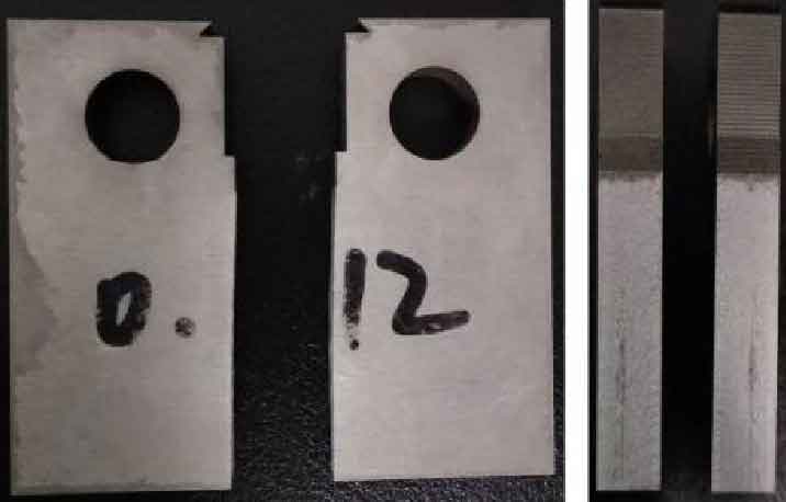
The stress intensity factor (SIF) at the crack tip is determined because the sharp crack satisfies the requirement of linear elastic fracture mechanics Δ K the crack tip of the compact tensile specimen used must be sharp. Therefore, it is necessary to pre crack the specimen before loading the fatigue crack growth test. In order to facilitate the precracking, the wire cutting method is used to cut a initiation notch with a width of 0.12 mm (the machining error is required to be no more than 0.02 mm) and a depth of 4 mm when processing the compact tensile specimen. The method of precracking used in this experiment is to load the alternating cyclic load on MTS 810 electro-hydraulic servo material experimental system on the basis of initiating the notch, and to prefabricate the fatigue precracking by gradually reducing the stress intensity factor at the crack tip. The length of prefabricated crack is 1 mm. The crack length measured by extensometer in the test starts from the midpoint of the line connecting the center of the loading hole and ends at the recorded time. Therefore, the measured crack length on the sample is actually composed of 4 mm original notch, 4 mm initiation notch, 1 mm pre crack and actual fatigue crack. The measured crack length a on the sample is equal to the sum of original notch length A0, initiation notch length A1, pre crack length A2 and actual fatigue crack length AF. its structure is shown in Fig. 3.

After the pre crack is finished, the 42CrMo steel compact tensile specimen is loaded formally. The experimental equipment is MTS 810 electro-hydraulic servo material experimental system described above. The loading was carried out at room temperature and atmospheric environment, using unidirectional axial loading. When the load ratio r = 0.1, the amplitude alternating load range is 4.95 kn; When the load ratio r = 0.6, the amplitude alternating stress range is 1.28 kn. When the loading waveform is sine wave and the loading frequency is f = 10 Hz. Until fatigue damage occurs, the specimen after failure is shown in Figure 4