The design methods for non circular helical gears mainly include analytical method, reduced tooth profile method, envelope method, etc. The analytical method solves the tooth profile equation of non circular helical gears through the meshing angle function, and its tooth profile accuracy is related to the spacing and number of tooth profile sampling points, which requires a large amount of calculation. The converted tooth profile method approximates the pitch curve at each tooth position as a standard spur gear indexing circle, determines the curvature center at each point, and draws the corresponding tooth profile based on the size of the curvature radius. Its computational complexity is small. According to Liu Yongping et al., the error between the analytical method and the converted tooth profile method does not exceed 2%. Therefore, the converted tooth profile method has a strong applicability in the design of non circular helical gears. The envelope method simulates the principle of generating tooth profiles using the generative method for machining helical gears, and the accuracy of the generated tooth profiles is related to the accuracy of the helical gear or hob tool and the step size of the envelope. The process of generating tooth profiles is relatively complex.
Compared to cylindrical helical gears, non circular helical gears also have the characteristics of smooth transmission, large overlap, and strong load-bearing capacity. There are two main design methods for non circular helical gears: the reduced tooth profile method and the envelope method. The former is based on designing the end face of non circular helical gears using this method, determining the helix of each tooth through the parameters of the base circle radius and helix angle, and finally completing the modeling of non circular helical gears through CAD modeling and generating them using 3D printing technology; The latter can be seen as the cutting motion between the non circular helical gear blank and the hob tool to generate the non circular helical gears tooth profile. Through the meshing relationship between the non circular helical gears and the hob tool, the tooth profile equation of the non circular helical gear can be obtained to complete the design of the non circular helical gear. The two methods each have their own emphasis. The design concept of the converted tooth profile method is simple, but the three-dimensional modeling has strong repeatability and is satisfied with low accuracy; The envelope method focuses more on manufacturing production and is commonly used in situations where high precision is required.
Taking the conversion tooth profile method as the core, a detailed overview of the modeling method for non circular helical gears is provided. At the same time, ZHY Gear used the involute helix equation for the first time to reconstruct a new non circular helical gear “helix” – the intersection line, and completed the modeling. Finally, perform kinematic simulation on the non circular helical gears model to check the meshing and interference of the main and driven wheels, in order to verify the rationality of the model.
1. Design of pitch curve related parameters for non circular helical gears
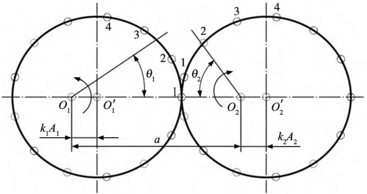
The pitch curves of the main and driven wheels are shown in Figure 1. O1 and O2 are the rotation centers of the main and driven wheels, respectively. O ′ 1 and O ′ 2 are the geometric centers of the main and driven wheels, respectively. The “○” on the pitch curve represents the position of the gear teeth. The two nodal curves always remain tangent. When the driving wheel rotates counterclockwise θ At an angle of 1, the driven wheel rotates clockwise accordingly θ 2 angles.
The polar coordinate expression formulas for the pitch curves of the main and driven wheels are:
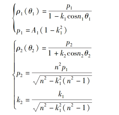
In the formula: n1 and n2 are the main variables, indicating the order of the driven wheel. n is the inverse ratio of the main variable and the order of the driven wheel, where n=n2/n1; K1 and k2 are the main components, with the eccentricity of the driven wheel and A1 and A2 being the main components. The length of the driven wheel is half the shaft length.
When the basic parameters of the driving wheel are determined, the relevant basic parameters of the driven wheel are determined. The basic parameter relationship between the main and driven wheels is:
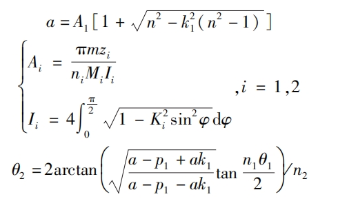
In the formula: a is the rotation center distance of the main and driven wheels, i=1,2 is the number of teeth of the main and driven wheels, zi is the number of teeth of the main and driven wheels, and the number of teeth of the helical gear starts from the meshing point, as shown in Figure 1; M is the modulus, and in non circular helical gears, it is the end face modulus mt; Ii is the circumference of the pitch curve of a non circular helical gears.
2. Relevant verification of non circular helical gears
The verification of non circular helical gears includes pressure angle verification, root cutting verification, and concavity and convexity verification. The verification formulas for the three are:
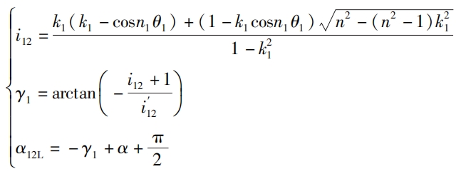
In the formula: α Is the tooth shape angle, i12 is the main and driven wheel transmission ratio function, α When the driving wheel (i=1) rotates counterclockwise, 12L is the pressure angle at which the left tooth profile works and ensures that α 12L ≤ 65 °.
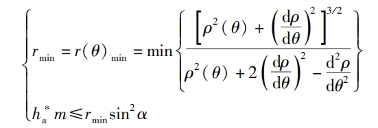
In the formula: rmin is the minimum curvature radius, h * a, m and α 0 represents the tooth top height coefficient, modulus, and tooth profile angle, which are all end face parameters h * at, mt, and in non circular helical gears α T.

In the formula, when ni=1, the gear is a 1st order elliptical helical gears, and there must be no internal concave.
3. Improvement of Helix for Non circular Helical Gears
In cylindrical helical gears, the helix obtained by intersecting the tooth profile surface with the indexing cylinder surface is projected onto the plane where the indexing circle is located, and the helix coincides with the indexing circle. According to the method of converting tooth profile, when determining the helix of a non circular helical gears, it is necessary to calculate the curvature center coordinates and corresponding indexing circle radius at each tooth position to determine the helix at the tooth position.
3.1 Defects in the helix of non circular helical gears
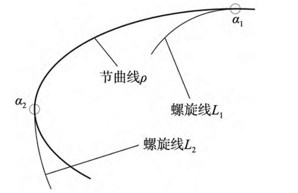
Due to the different curvature of the pitch curve at each tooth, the corresponding helix deviation varies. As shown in Figure 2, project the spiral line onto the plane where the pitch curve is located, on the pitch curve ρ At the point of smaller curvature a1, the helix L1 is biased inward; On the nodal curve ρ The curvature is larger at a2, and the helix L2 is off center. Therefore, the uneven deviation of the helical teeth generated by the helix has a significant impact on the meshing performance of non circular helical gears. It is necessary to improve the helix of non circular helical gears.
3.2 Characteristics of involute helical surfaces
As shown in Figure 3, in the relative coordinate system σ On 1x1y1z1, when the surface KMN undergoes pure rolling along the base cylinder surface Rb with a radius of rb, the helix angle of the base cylinder is the angle between one of its upper lines and the generatrix JKN on the base cylinder β The surface ABCDE formed by the oblique line KM of b is an involute helical surface, and the path ABC formed by the intersection point K of the oblique line KM and the base cylinder generatrix JKN is the base cylinder helix, and the oblique line KM is always tangent to the base cylinder helix ABC.
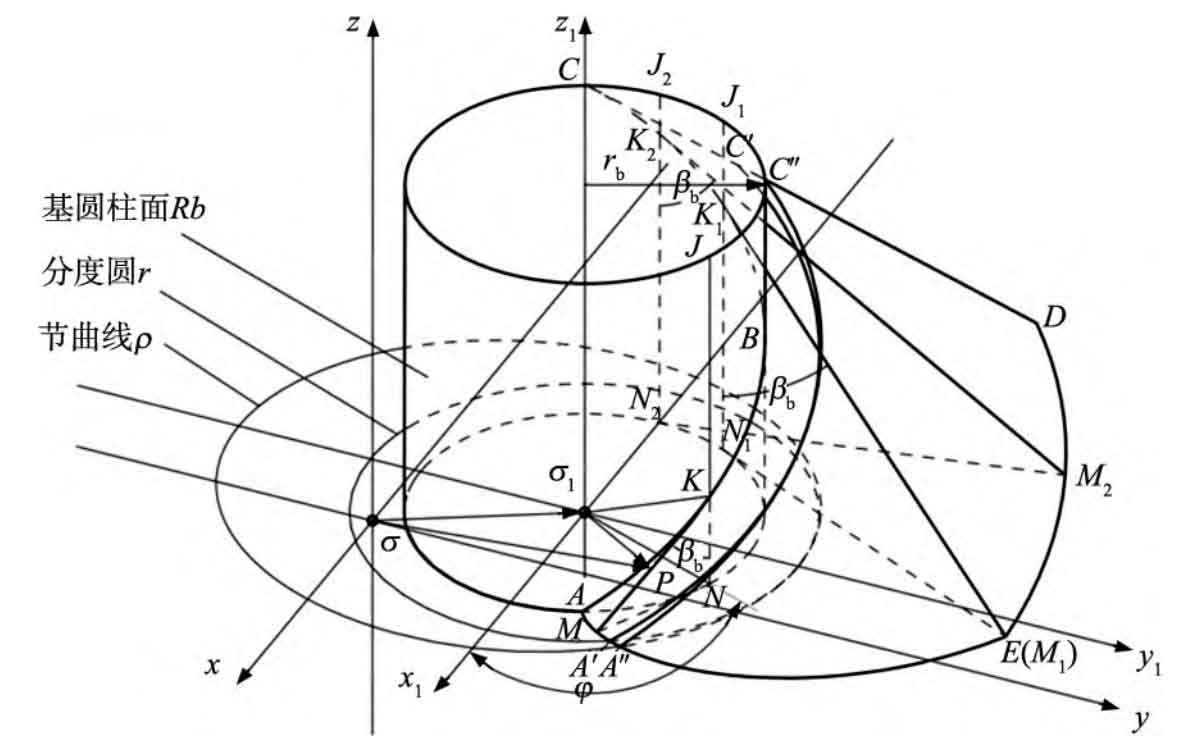
According to the research of Zhou Jianjun, Xiao Yang, and others, if an involute spiral surface is truncated from any spatial plane z1=C (C is an arbitrary constant), the intersection of the two is called an involute. For cylindrical helical gears, when C=0, the cut involute AE is the involute of the helical gear end face; When C=B (B is the tooth width), the cut involute is the involute of the other end face of the helical gears. The spatial curve A ′ C ′ intercepted by the cylindrical surface and the involute helical surface ABCDE formed by the indexing circle r corresponding to the base cylinder is the helix of the helical gears.
In the relative coordinate system σ On 1x1y1z1, the surface parameter equation of the involute helical surface is:
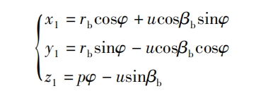
In the formula: p=rbtan β B, β B is the helix angle of the base cylinder, rb= σ 1N is the base circle radius, φ When the surface KMN rolls on the base cylinder, the angle at which the tangent KN intersecting with the base cylinder passes over the base cylinder; PK=u, the line segment from the tangent point K of the base cylinder helix ABC and PK to any point P on the involute helical surface; KN=p φ, Spiral ascent motion transitions through angles φ The distance at which the tangent point K rises.
3.3 Helix solution for non circular helical gears
To overcome the problem of uneven helix deviation in non circular helical gears, it is proposed to determine a curved cylindrical surface that intersects with the involute helical surface ABCDE. The intersected line is the spatial curve A “C”, which is no longer a helix and is referred to as the intersected line, which will not be repeated later. Project the intersection line A “C” onto the plane where the pitch curve is located, which coincides with the pitch curve, solving the problem of uneven deviation of the helix. The following steps will be taken to solve the intersection line A “C”:
Step 1: According to Figure 3, adjust the absolute coordinate system σ Xyz is fixed at the rotation center O of a non circular helical gears, and the relative coordinate system is adjusted accordingly σ Expand 1x1y1z1 to σ Jxjyjzj (j represents the tooth number, i.e. the jth tooth) is fixed at the curvature center cj of the tooth at the end face of the non circular helical gears.
Step 2: Find the curvature center of the j-th non circular helical gears tooth corresponding to it in the coordinate system σ Vector representation in xyz.
The polar coordinates corresponding to the jth non circular helical gears tooth on the pitch curve are:( θ J, ρ J( θ j) (0), obtain the curvature center cj in the absolute coordinate system through transformation σ Coordinate cj under xyz (= σσ j) For:
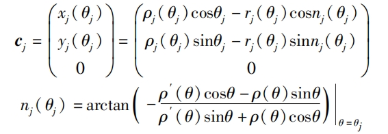
In the formula: rj( θ j) The curvature radius at the tooth of the jth non circular helical gears, nj( θ j) Indicates the inclination angle of the normal equation at the j-th tooth.
Similarly, the curvature center coordinates of other teeth can be obtained by obtaining the curvature center coordinate set matrix C3 × z=(c1… cj… cz), where z is the number of teeth and j ≤ z.
Step 3: According to the formula parameter equation, calculate its vector form, that is, the vector equation of the involute helical surface (ABCDE) j at the j-th non circular helical gears tooth is expressed as:

The parameter equation form is:

In the formula: pj=rbjtan β b. RBJ is the base circle radius corresponding to the jth non circular helical gears tooth.
Similarly, the vector set matrix P3 × z=(p1… pj… pz) of the involute helical surfaces of other gears can be obtained.
Step 4: Place the involute helical surface (ABCDE) j at the j-th tooth in the absolute coordinate system σ Represent and write the nodal curve cylinder equation in xyz. According to Figure 3, the involute helical surface (ABCDE) j is located in the absolute coordinate system σ Represented in xyz as:

According to the formula, oj is specifically expressed as:

Its functional form is:

After the above analysis, the vector set matrix O3 × z=(o1… oj… oz) of all involute helical surfaces is represented as:

According to the formula, the planar nodal curve ρ ( θ) The Cartesian cylindrical equation is:
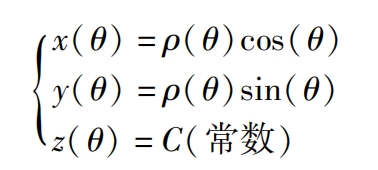
Its functional form is:

The Cartesian coordinates of non circular helical gears teeth at the pitch curve can be calculated using a formula as T3 × z=(t1… tj… tz).
Step 5: Calculate the intersection line A “jC” j at the jth gear tooth. The equation of the pitch curve cylindrical surface is combined with the equation of the involute helical surface oj at the jth gear tooth, and the intersection line A “jC” j between the two can be obtained.
Simplify the formula and combine it to obtain the general equation Gj for the intersection line of the jth non circular helical gears tooth( θ J, φ j. Uj, θ,ρ ( θ)) For:

Integrate the above steps and write the general equation for the intersection line A “jC” j corresponding to the teeth of all non circular helical gears. The vector set G solved by combining the formulas is:

Due to the complexity of the intersection equation, it can only be represented by the joint of the nodal curve cylindrical surface and the involute spiral surface. However, in subsequent modeling operations, curve intersection operations can be performed to obtain the intersection lines A “j, C” j.
