
From my perspective as someone deeply involved in manufacturing, the art and science of gear cutting represent a fascinating intersection of precision engineering, historical legacy, and relentless adaptation. The process of shaping the teeth of a gear, especially for critical applications like automotive differentials, is not merely a machining step; it is a foundational activity that dictates the performance, noise, and longevity of the entire drivetrain. For decades, one name has been synonymous with the pinnacle of spiral bevel and hypoid gear cutting: Gleason. The dominance of their machines in producing automotive hypoid gears has been near-absolute, a testament to the effectiveness and proprietary nature of their method. This unique position has created a specific ecosystem where end-users must become innovators, adapting and evolving these specialized systems to meet ever-changing market demands.
The core Gleason method for hypoid gear cutting is a masterpiece of mechanical synchronization. Its defining characteristic has been the generating principle, where the coordinated motion of the cutter head and the workpiece meticulously carves out the complex, curvature-matching tooth surfaces. The fundamental relationship governing this can be simplified for understanding as a continuous function linking tool position and workpiece rotation. The basic kinematic chain ensures the cutter follows a predetermined path relative to the gear blank. The mathematical representation often starts from the equation of the generated gear surface \(\Sigma_g\), derived from the family of tool surfaces \(\Sigma_t\) undergoing the generating motion. A simplified form can be expressed as:
$$
\vec{r}_g(u, \theta, \phi) = M_{wg}(\phi) \cdot M_{tw}(\theta) \cdot \vec{r}_t(u)
$$
Where:
\(\vec{r}_t(u)\) is the position vector of a point on the cutter surface.
\(M_{tw}(\theta)\) is the transformation matrix representing the relative positioning (tilt, offset) of the cutter to the workpiece.
\(M_{wg}(\phi)\) is the transformation matrix representing the rotation of the workpiece.
\(u, \theta, \phi\) are the surface and motion parameters.
The exact form of these matrices encapsulates the patented Gleason geometry. For nearly a century, this mechanical genius remained largely unchanged, protected by patents and a deep technological moat. However, the static nature of the core principle did not imply stagnation for the end-user. On the contrary, it forced manufacturing engineers like myself to focus our ingenuity on optimizing everything *around* the core gear cutting process to survive in a dynamic industrial landscape.
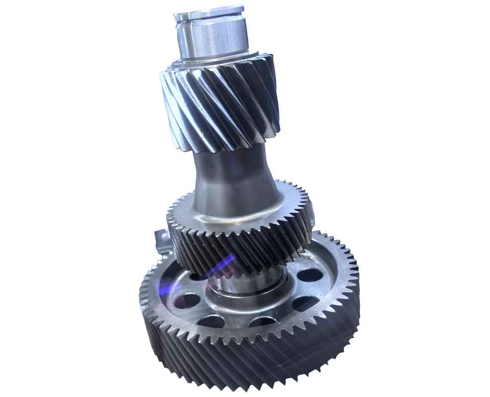
The external pressures for change have been multifaceted and relentless. The table below summarizes the key environmental shifts and their direct implications for a hypoid gear cutting production line:
| Environmental Change | Implication for Gear Cutting Operations |
|---|---|
| Economic Volatility (e.g., Oil Crises, Inflation) | Intense pressure to reduce manufacturing cost per piece, focusing on energy efficiency, material yield, and labor productivity. |
| Market Demand for Higher Product Grades | Requirement for superior gear quality: lower noise, higher load capacity, longer life. This demands tighter tolerances and more consistent gear cutting processes. |
| Proliferation of Vehicle Models & Variants (Increased Variety) | Dramatic increase in changeover frequency. The traditional lengthy setup times for gear cutting machines become a major bottleneck. |
| Intensified Global Competition | Necessitates both lower cost and higher quality simultaneously. Lean manufacturing and zero-defect strategies become critical. |
| Advancements in Machine Tool Technology (CNC, Automation) | Creates opportunity but also pressure to modernize. Legacy machines risk becoming obsolete if not integrated with new control and monitoring systems. |
Relying solely on the original equipment manufacturer (OEM) for solutions to these challenges is often impractical or economically unviable. The OEM’s roadmap is broad, while our needs are specific and immediate. Therefore, the most effective response emerges from within—leveraging the profound, hands-on knowledge of maintenance technicians and process engineers who live with the machines daily. This in-house capability transforms from a cost center into a strategic innovation hub. The general strategy for adaptation can be visualized as a continuous cycle: 1) **Monitor** environmental and internal performance signals; 2) **Diagnose** specific constraints or wastes in the gear cutting process; 3) **Conceive & Design** mechanical, control, or procedural modifications; 4) **Implement** the improvements using in-house skills; and 5) **Standardize** the successful solutions across all relevant machines.
A prime example of this in-house evolution is found in the critical area of workpiece handling and fixturing on Gleason pinion gear cutting cells. Modern Gleason centers, like the theoretical “Gleason Phoenix” cell mentioned in source materials, integrate multiple operations (rough cutting, chamfering, finishing) linked by automated loaders and conveyors. The fixturing—the mechanism that picks up, locates, and clamps the raw forging or semi-finished pinion—is the handshake between automation and precision. Any inefficiency here cascades into downtime and quality issues. The traditional fixture design was a marvel of mechanical dedication but a nightmare for flexibility. Each pinion type, defined by its shaft geometry and tooth count, required a dedicated set of locators, clamps, and probing fixtures. The setup change procedure was arduous and time-consuming.
Let’s analyze the traditional vs. in-house improved fixture design mathematically, focusing on setup time. The total setup time \( T_{setup} \) can be modeled as the sum of the time for individual tasks:
$$
T_{setup}^{old} = \sum_{i=1}^{N} t_i
$$
Where \( N \) could be 5 or more tasks: changing dedicated cone locators, adjusting the angular indexer position, setting the gear tip air probe, setting the tooth thickness air probe, and even changing the entire fixture body for different tooth counts. Each task \( t_i \) involved manual adjustment, trial cuts, and verification, often taking 30 minutes or more in total.
The in-house engineered solution targeted each term in this equation. The breakthrough was a shift in datum strategy. Instead of using a conical shaft surface (which varies between parts), the new design clamped axially against the pinion’s end face—a more consistent feature. This eliminated the need for dedicated cone locators (\( t_1 \rightarrow 0 \)). The angular indexing mechanism was simplified from multiple pins to a single pin system, decoupling it from the tooth count and removing the need for fixture body changes (\( t_5 \rightarrow 0 \)). The positions of the air probes were linked mechanically to the indexer or made easily adjustable with visible gauges, drastically reducing \( t_3 \) and \( t_4 \). The new setup time model becomes:
$$
T_{setup}^{new} = t_2′ + \epsilon
$$
Where \( t_2′ \) is a greatly simplified index position setting and \( \epsilon \) represents minimal probe touch-up time. The reduction is often an order of magnitude, turning a major changeover into a quick, repeatable routine. This is a direct result of applying in-house gear cutting process knowledge to redesign the tooling interface.
| Aspect | Traditional Fixture Design | In-House Improved Fixture Design |
|---|---|---|
| Primary Datum | Conical shaft surface (variable) | Pinion end face (consistent) |
| Indexing Mechanism | Multiple pins, tooth-count dependent | Single pin, tooth-count independent |
| Probe Adjustment | Fully manual, requires trial cuts | Mechanically linked or gauge-referenced |
| Fixture Body | Multiple dedicated bodies required | One universal body for families of parts |
| Typical Changeover Time | 30-60 minutes | 5-10 minutes |
| Impact on Flexibility | Low; changeovers are avoided | High; supports high-mix production |
The pursuit of adaptation extends far beyond fixturing. Consider the overarching goal of improving Overall Equipment Effectiveness (OEE) for the gear cutting department. OEE is the product of Availability (A), Performance (P), and Quality (Q) rates:
$$
OEE = A \times P \times Q
$$
Internal improvements target each factor. **Availability** is attacked by reducing setup times (as above) and implementing predictive maintenance. For instance, monitoring the cutting force during gear cutting can predict tool wear. The average cutting force \( F_c \) can be related to flank wear \( VB \) by an empirical relationship:
$$
F_c = k_1 + k_2 \cdot VB^{n}
$$
By tracking \( F_c \) in real-time, we can schedule tool changes proactively, preventing catastrophic failure and unplanned downtime, thus maximizing ‘A’. **Performance** is improved by optimizing cutting parameters. The classic Taylor’s Tool Life equation for gear cutting tools can be adapted:
$$
VT^n = C
$$
Where \( V \) is cutting speed, \( T \) is tool life, and \( n \) and \( C \) are constants. Through in-house experimentation, we find the optimal balance \( V_{opt} \) that maximizes metal removal rate without excessively degrading tool life, thereby improving ‘P’. **Quality** is enhanced through process control. Statistical Process Control (SPC) charts for key gear characteristics like tooth profile error \( \Delta f_f \) or pitch error \( \Delta f_p \) are maintained. Process capability indices are calculated:
$$
C_{pk} = \min\left( \frac{USL – \mu}{3\sigma}, \frac{\mu – LSL}{3\sigma} \right)
$$
Where \( USL/LSL \) are the specification limits for the gear characteristic, and \( \mu \) and \( \sigma \) are the process mean and standard deviation. In-house projects aim to reduce \( \sigma \) (variation) and center \( \mu \), driving \( C_{pk} \) above 1.67 for true robust quality, directly improving ‘Q’.
Another fascinating area of in-house innovation is in auxiliary monitoring technology. While not part of the gear cutting machine itself, technologies like reversible temperature-indicating labels (often called thermochromic patches) play a vital role in safeguarding the process. These patches are applied to critical points: spindle housing, bearing blocks, hydraulic power units, or electrical cabinets near the gear cutting machine. Their color change at a specific temperature \( T_{alert} \) provides a permanent, visual record of overheating incidents. This is a simple yet powerful form of condition monitoring that supplements electronic sensors. The underlying principle is based on the irreversible chemical or physical change of leuco dyes or liquid crystals. From a reliability engineering standpoint, they help in identifying hotspots that could lead to failures, contributing to improved Availability (A) in the OEE equation. Their implementation is a low-cost, high-impact in-house reliability improvement.
The journey of a Gleason gear cutting machine, from a standalone, mechanically programmed unit to an integrated, adaptable cell, mirrors the broader journey of manufacturing. The OEM provides the foundational lexicon—the generating principle, the basic machine structure. But the poetry of efficient, flexible, and high-quality production is written by the users. We dissect the kinematics, not to replicate them, but to understand their constraints. We redesign fixtures, not to invalidate the original design, but to extend its life and relevance. We instrument the process, not because the machine is lacking, but because our ambition for data-driven perfection exceeds its original scope. The modern landscape now includes new entrants in the hypoid gear cutting machine market, applying principles like full CNC contouring. This competition validates the importance of the field and provides new options. However, the core lesson remains: the most valuable asset is not any single machine, but the accumulated, living knowledge of the team that operates, maintains, and continuously adapts it. The future of gear cutting excellence lies in this symbiosis between enduring mechanical principles and perpetual human-led innovation.