
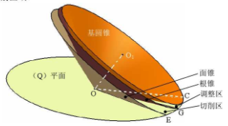
This paper takes the concave tooth surface of right-hand spiral bevel gear as an example to analyze and study the generation principle of concave tooth surface cutting. It can be seen from the analysis that the generating process of the concave tooth surface of the right-hand spiral bevel gear is: the generating line of the tooth surface rolls on the basic cone with the tangent plane (q) plane of the basic cone, winds from the big end to the small end, and expands from the basic cone to the face cone to generate the concave tooth surface of the spiral bevel gear. As we all know, in the process of real tooth cutting, it is impossible for the blade to feed from the base cone of the blank according to the generation direction of the tooth surface, and then cut out in the direction of the face cone. However, if the reverse movement of generating movement of tooth surface is taken as the cutting movement of tooth surface, that is to say, the generating line of tooth surface is taken as the cutting edge of tooth surface, and the generation of tooth surface is carried out from the face cone to the root cone, and from the small end of blank to the large end, the whole cutting process of tooth surface is just opposite to the generation process of tooth surface. This method is feasible and can be used to cut the tooth surface of spiral bevel gear without principle error. In this paper, based on the theory of generating line gear cutting, a new method of machining spiral bevel gear tooth surface is put forward.
In order to understand the two key areas in the process of tooth cutting more intuitively: the adjustment area ψ and the cutting area angle μ, the CATIA software is used to establish a three-dimensional model of (q) plane tangent to the base cone and intersecting with the root cone and the face cone, as shown in Figure 2.11. It is found that the (q) plane is tangent to the base cone in the straight line OC, and intersects with the root cone and the face cone in the straight line og and OE respectively, thus forming the adjustment area between the base cone and the root cone and the cutting area between the root cone and the face cone.
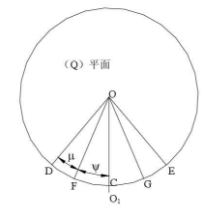
In order to facilitate the analysis of the relationship between the various motions required for the generation of tooth surface cutting based on the generation principle of spherical involute tooth surface, using CATIA’s engineering drawing function, taking the (q) plane as the reference plane, the three-dimensional view of Fig. 2.11 is projected in the front view, as shown in the figure.
The coordinate system is established on the basis of the graph, with o point as the origin of the rectangular coordinate system, the direction of horizontal right is the positive direction of X axis, and the direction of vertical up is the positive direction of Y axis. And establish the cutting area and adjustment area needed in the actual cutting process, as shown in Figure 2.13. The shadow part of the area dhjf and the area gkie is the area to be processed with an angle of μ, while the trapezoid jkgf area is two symmetrical adjustment areas with an angle of ψ, which are also non machining areas.
According to the analysis of the generation principle of tooth surface and the generation line of tooth surface in this section, the generation line of tooth surface – arc line AB is used as the cutting edge, and the reverse movement of the generation movement of tooth surface is used as the cutting movement, so that the tooth surface of spiral bevel gear without principle error can be machined. As shown in the figure, the arc blade arc line AB is located on the (q) plane, the radius of the blade is r, and the tool position is the distance between the center of the blade and the center of the (q) plane is Q. When the generating line ab of the tooth surface rotates with the angular velocity ω around the o-point in the (q) plane, the gear blank rotates with the angular velocity ω around the o-point in the (q) plane, the gear blank rotates with the angular velocity ω of the ω 1, and the ω and ω 1 rotate, and the ω and ω 1 maintain the 1-maintaining relationship At the same time, the generating line of the tooth surface will roll on the base cone to cut the concave tooth surface of the spiral bevel gear along the direction of the face cone to the base cone and the small end to the large end. In order to cut the tooth surface of spiral bevel gear completely, the movement track of tooth generation line AB must cover the whole cutting area, that is, the tooth generation line AB must rotate with (q) plane to the A1 tooth generation line AB in the figure must rotate with (q) plane to the A1B tooth generation line AB in the figure must rotate with (q) plane to the position of a1b1b1 in the figure. However, it is obvious from Fig that when the occurrence line of tooth surface moves from position AB to position A1, it is found that when the occurrence line of tooth surface moves from position AB to position When a1b1b1b1 is 1, when cutting out the complete tooth surface of spiral bevel gear, it is absolutely not allowed to over cut the shadow part of the mesh in the adjustment area, so a motion must be added in the process of cutting the tooth surface to prevent over cutting in the adjustment area in the process of cutting the tooth surface.
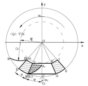
Because the blade is an arc-shaped blade, and the arc has the characteristics of rotation and coincidence around its own geometric rotation center, therefore, after comprehensive analysis, in the process of cutting the tooth surface, a tooth surface generating line can rotate around its own rotation center to withdraw the tool. Not only can it prevent over cutting, but also the arc line coincides after rotating around the geometric center of the arc blade itself, which does not change the shape of the generated spiral bevel gear tooth surface. Next, the rotation speed of the blade around its geometric center is calculated. In this paper, the speed is defined as the rotation speed of the blade, and the size is: ω 0. In this paper, the speed is defined as the rotation speed of the blade, and the size is: ω 0. In this paper, the rotation speed of the geometric center is defined as the rotation speed of the blade, which is ω 0. In order to facilitate the motion analysis, the blade with a speed of ω, which should be carried out synchronously in the actual machining, is rotated around the o-point and the speed of ω 0 is The rotation of the 0 of ω 0 is divided into two steps, which can greatly simplify the calculation of the movement, and does not violate the movement relationship of the blade. Only in the actual cutting process of the tooth surface, the above two steps can be carried out synchronously.