
The development of power transmission systems constantly seeks advancements in efficiency, weight reduction, and reliability. Among innovative solutions, face gear drives present a compelling alternative to conventional bevel or worm gear sets. A face gear is characterized by its tooth geometry which is generated on a planar or conical surface, meshing with a spur or helical pinion. This unique configuration offers significant advantages, including a high degree of contact ratio, inherent insensitivity to axial misalignment of the pinion, and the absence of axial thrust loads on the mating cylindrical gear. These attributes make face gear drives particularly attractive for demanding applications such as aerospace transmissions, where weight savings and reliability are paramount.
Historically, the realization of functional face gear drives has been contingent upon the development of viable and precise manufacturing methods. The geometric complexity of the face gear tooth surface, which is a conjugate envelope to the pinion tooth surface, necessitates specialized machining techniques. Among these, the process of gear shaping using a pinion-shaped cutter has emerged as a primary and practical method for generating face gears. This paper, from a first-person analytical perspective, delves into the fundamental geometric principles underlying this gear shaping process. A critical aspect of any generative machining process is the potential for interference between the theoretical tooth form and the transient surfaces generated by the cutter during its feed motion. Therefore, a thorough investigation into the relative positioning of the theoretical envelope surface and the so-called “process surface” created during radial infeeding is essential to validate the feasibility of the gear shaping method.
The core of the analysis lies in establishing a rigorous mathematical model for the gear shaping operation. We consider an orthogonal face gear drive, where the axes of the face gear and the generating pinion-shaped cutter are perpendicular and intersect. The machining simulation involves two fundamental motions: the generating roll motion between the cutter and the workpiece, and the radial feed motion of the cutter towards the face gear axis. To model this, we define a series of coordinate systems that capture the kinematics of the gear shaping process.
Let us denote the pinion-shaped cutter’s coordinate system as \( S_1(X_1, Y_1, Z_1) \), fixed to the cutter with its origin at the cutter center. The tooth surface of the cutter is a standard involute helicoid. In this system, a point on the cutter’s involute surface can be expressed using two independent geometric parameters: the pressure angle \( \alpha \) and a parameter \( \gamma \) related to the tooth width. The coordinates \( (x_1, y_1, z_1) \) are given by:
$$
\begin{aligned}
x_1 &= \frac{r_b \sin(\text{inv}\alpha)}{\cos\alpha}, \\
y_1 &= \frac{r_b \cos(\text{inv}\alpha)}{\cos\alpha}, \\
z_1 &= -\frac{r_b \tan\gamma}{\cos\alpha},
\end{aligned}
$$
where \( r_b \) is the base circle radius of the cutter and \( \text{inv}\alpha = \tan\alpha – \alpha \) is the involute function. This surface, \( \mathbf{r}_1(\alpha, \gamma) \), serves as the tool surface in the gear shaping operation.
To derive the theoretical tooth surface of the face gear, we consider the pure rolling motion between the cutter and the blank. A fixed coordinate system \( S_f(X_f, Y_f, Z_f) \) is attached to the face gear blank. The cutter coordinate system \( S_1 \) is transformed into \( S_f \) through a sequence of rotations and translations that simulate the generating motion. The key kinematic parameter is the rotation angle \( \phi_1 \) of the cutter. The face gear blank rotates by an angle \( \phi_2 \), where \( \phi_2 = i \cdot \phi_1 \) and \( i \) is the gear ratio (typically \( i = N_1 / N_2 \), where \( N_2 \) is the number of teeth on the face gear). The coordinate transformation from \( S_1 \) to \( S_f \) involves rotating \( S_1 \) by \( \phi_1 \) about its axis, translating it to account for the nominal mounting distance \( d \), and finally rotating by \( \phi_2 \) about the face gear axis to arrive at \( S_f \). The transformed surface family in \( S_f \) is:
$$
\mathbf{r}_f(\alpha, \gamma, \phi_1) = \mathbf{M}_{f,1}(\phi_1) \cdot \mathbf{r}_1(\alpha, \gamma),
$$
where \( \mathbf{M}_{f,1}(\phi_1) \) is the \( 4 \times 4 \) homogeneous transformation matrix encapsulating the described motions. According to the theory of gearing, the envelope of this single-parameter family of surfaces, defined by the parameter \( \phi_1 \), yields the theoretical face gear tooth surface. The necessary condition for the envelope (the equation of meshing) is given by the scalar triple product being zero:
$$
\frac{\partial \mathbf{r}_f}{\partial \phi_1} \cdot \left( \frac{\partial \mathbf{r}_f}{\partial \alpha} \times \frac{\partial \mathbf{r}_f}{\partial \gamma} \right) = 0.
$$
Solving this equation for \( \phi_1 \) in terms of \( \alpha \) and \( \gamma \) and substituting back into \( \mathbf{r}_f \) provides the mathematical representation of the theoretical face gear tooth surface, \( \mathbf{R}_f(\alpha, \gamma) \). This surface represents the ideal outcome of the gear shaping process without considering the tool feed path.
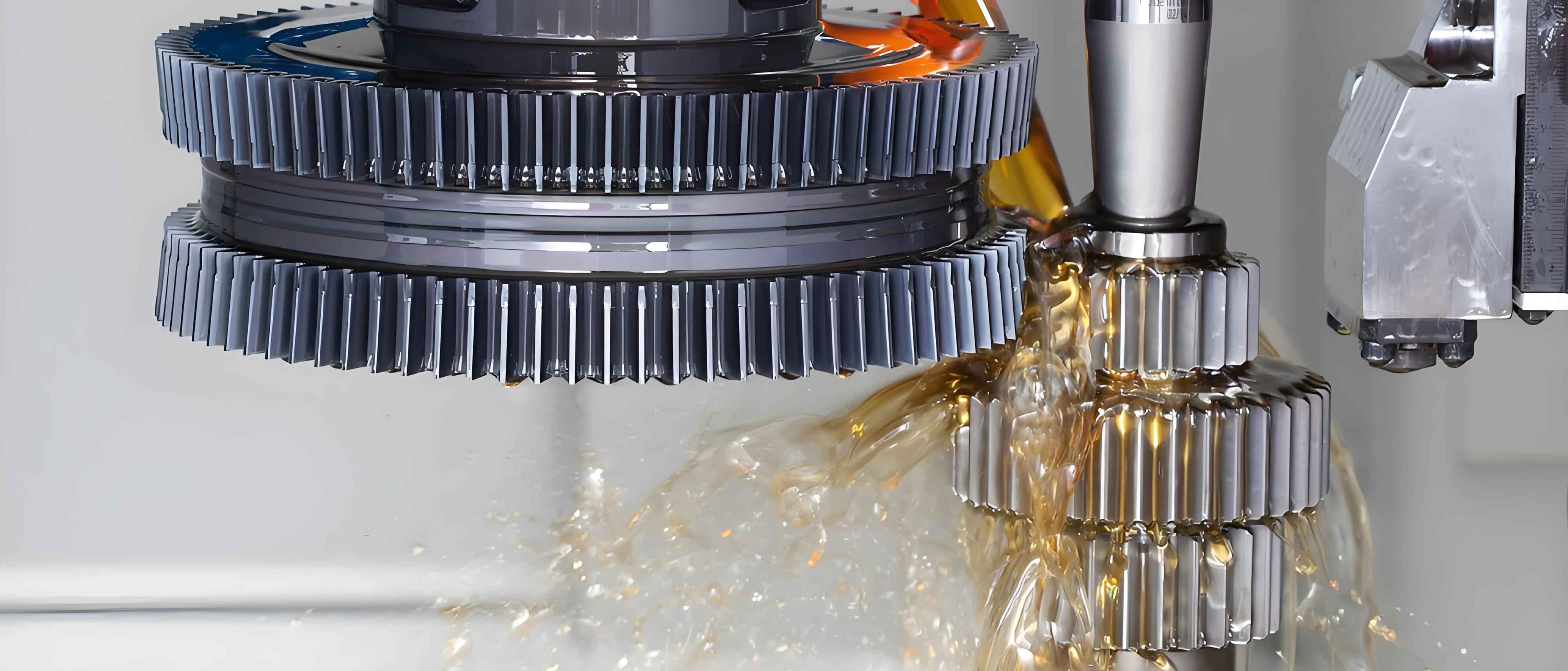
However, in a real gear shaping machine, the cutter is not merely rolled against the blank; it also undergoes a radial feed motion \( s \) towards the center of the face gear to achieve the full tooth depth. This radial feed, typically proportional to the generating angle \( \phi_1 \) (i.e., \( s = n \cdot \phi_1 \), where \( n \) is the radial feed rate coefficient), modifies the kinematics. The coordinate transformation for this “process” now includes an additional translation component along the radial direction before the generating rotation. The resulting surface family generated during this combined motion (feed + roll) is:
$$
\mathbf{r}_p(\alpha, \gamma, \phi_1) = \mathbf{M}_{p,1}(\phi_1, n) \cdot \mathbf{r}_1(\alpha, \gamma),
$$
where \( \mathbf{M}_{p,1}(\phi_1, n) \) is the transformation matrix incorporating the radial feed \( s \). The envelope of this family, satisfying a similar equation of meshing condition, defines the “process surface”, \( \mathbf{R}_p(\alpha, \gamma, n) \). This surface represents the actual path swept by the cutter teeth during the machining operation. A critical question for the feasibility of gear shaping is: Does this process surface \( \mathbf{R}_p \) ever intersect or gouge the desired theoretical tooth surface \( \mathbf{R}_f \)?
To analyze this, we investigate the relative position between \( \mathbf{R}_f \) and \( \mathbf{R}_p \) for a given point on the tool surface defined by \( (\alpha, \gamma) \). Conceptually, for successful material removal without interference, the process surface at any instant should lie entirely on the “stock side” of the final theoretical surface—that is, in the region from which material is to be removed. A numerical simulation is indispensable for this analysis. The following table summarizes the key parameters used for such a simulation, representative of a practical gear shaping setup.
| Parameter | Symbol | Value |
|---|---|---|
| Module | \( m \) | 5 mm |
| Number of Cutter Teeth | \( N_1 \) | 20 |
| Pressure Angle (at Ref. Circle) | \( \alpha_0 \) | 20° |
| Gear Ratio (Cutter to Face Gear) | \( i \) | 1/5 |
| Mounting Distance | \( d \) | 240 mm |
| Face Width | \( B \) | 60 mm |
| Radial Feed Rate Coefficient (Varied) | \( n \) | 0.1, 1.0, 10.0 mm/rad |
Using computational software (e.g., MATLAB), the equations for \( \mathbf{R}_f \) and \( \mathbf{R}_p \) are solved and plotted. The simulation involves calculating points across the entire active profile and face width for both surfaces under different radial feed rates \( n \). The results consistently show a clear and distinct spatial relationship. Regardless of the value of \( n \)—whether it is a slow feed (\( n=0.1 \)), a moderate feed (\( n=1.0 \)), or a fast feed (\( n=10.0 \))—the process surface \( \mathbf{R}_p \) always lies on one consistent side of the theoretical surface \( \mathbf{R}_f \). To determine if this side is the material removal side, we utilize the fact that the theoretical surface is the conjugate to the pinion. The direction of the relative velocity between the cutter and the gear blank at the point of contact, dictated by the kinematics of pure rolling, points towards the region to be removed. Analysis of this velocity vector field confirms that the process surface resides precisely within this designated material removal zone.
| Aspect | Theoretical Tooth Surface (\( \mathbf{R}_f \)) | Process Surface (\( \mathbf{R}_p \)) |
|---|---|---|
| Governing Kinematics | Pure rolling motion only (generation). | Combined rolling and radial feed motion. |
| Mathematical Model | Envelope of \( \mathbf{r}_f(\alpha, \gamma, \phi_1) \). Eq. of meshing: \( f(\alpha, \gamma, \phi_1)=0 \). | Envelope of \( \mathbf{r}_p(\alpha, \gamma, \phi_1, n) \). Modified eq. of meshing: \( f_p(\alpha, \gamma, \phi_1, n)=0 \). |
| Dependency | Independent of feed rate \( n \). | Directly dependent on feed rate \( n \). |
| Physical Meaning | Ideal, final form of the face gear tooth. | Transient surface swept by cutter during machining infeed. |
| Spatial Position (Result) | Defines the final gear boundary. | Consistently lies on the material removal side of \( \mathbf{R}_f \). |
This result is fundamental. It demonstrates that during the gear shaping process, the moving cutter will only remove material that lies outside the final theoretical form and will not inadvertently cut into the desired tooth surface itself. In other words, no gouging or interference occurs between the process envelope and the target geometry. This mathematical proof establishes the foundational feasibility of using a pinion-shaped cutter for the gear shaping of orthogonal face gears.
The validity of this conclusion is further reinforced by practical manufacturing trials. Based on this analytical assurance, a physical gear shaping operation can be confidently executed. Using a standard gear shaper machine equipped with a pinion-shaped cutter conforming to the design parameters (e.g., module \( m=2 \), number of teeth \( N_1=20 \)), a successful face gear workpiece with a high tooth count (e.g., \( N_2=98 \)) can be produced. The machined component will exhibit the characteristic face gear tooth form, visually confirming the correctness of the geometric and kinematic models. The entire gear shaping process, from blank to finished gear, relies on the precise coordination of motions derived from the equations above.
Beyond establishing feasibility, the mathematical model allows for the optimization of the gear shaping process. Key parameters such as the radial feed rate \( n \) can be studied not for interference (which is now proven absent) but for their effect on surface finish, machining time, and cutter wear. Furthermore, the model can be extended to analyze more complex scenarios, such as the gear shaping of non-orthogonal or offset face gear drives, which require additional transformations in the coordinate system setup. The equation of meshing becomes more complex but remains the cornerstone of the analysis.
In conclusion, the detailed investigation into the geometry of gear shaping for face gears provides a rigorous verification of the method’s validity. By establishing coordinate systems for both the theoretical generation and the practical feed motion, deriving the corresponding envelope surfaces, and numerically analyzing their spatial relationship, we conclusively show that the process surface does not interfere with the theoretical tooth profile. This clear spatial separation guarantees that the gear shaping technique is a viable and robust method for manufacturing precise orthogonal face gears. The successful transition from this analytical proof to physical part manufacturing underscores the power of geometric modeling in advanced gear engineering. The methodology outlined here forms a template for analyzing other generative gear manufacturing processes, ensuring their feasibility before costly empirical trials are undertaken.