
The pursuit of advanced power transmission solutions across demanding sectors such as robotics, aerospace, and precision instrumentation has continuously driven innovation in gear design. Among various transmission types, screw gears, particularly worm drives, are renowned for their compactness, high torque capacity, and ability to achieve large speed reduction ratios in a single stage. A significant evolution in this domain is the development of the planar enveloping internal meshing screw gear. This configuration presents a paradigm shift from the traditional external meshing worm gear, offering unique advantages like the potential for simultaneous multi-output load distribution from a single worm. This inherent capability makes it exceptionally suitable for complex machinery requiring synchronized or distributed power from a central source. The core of its design lies in the generating plane, a conceptual tool surface whose spatial orientation, defined by the generating plane inclination angle, fundamentally dictates the geometry of the worm tooth flank and the ensuing meshing characteristics. Consequently, a thorough investigation into the influence of this critical parameter is paramount for unlocking the optimal performance of these novel screw gears.
This article delves into a comprehensive analysis of the planar enveloping internal meshing screw gear transmission. We begin by establishing the fundamental mathematical framework based on gear meshing theory. Subsequently, we derive the key equations governing contact and analyze a crucial performance metric: the induced normal curvature. Using numerical methods, we systematically explore how the generating plane inclination angle affects this metric under varying design conditions, ultimately identifying its optimal range to enhance the overall meshing performance and load-bearing capacity of these advanced screw gears.
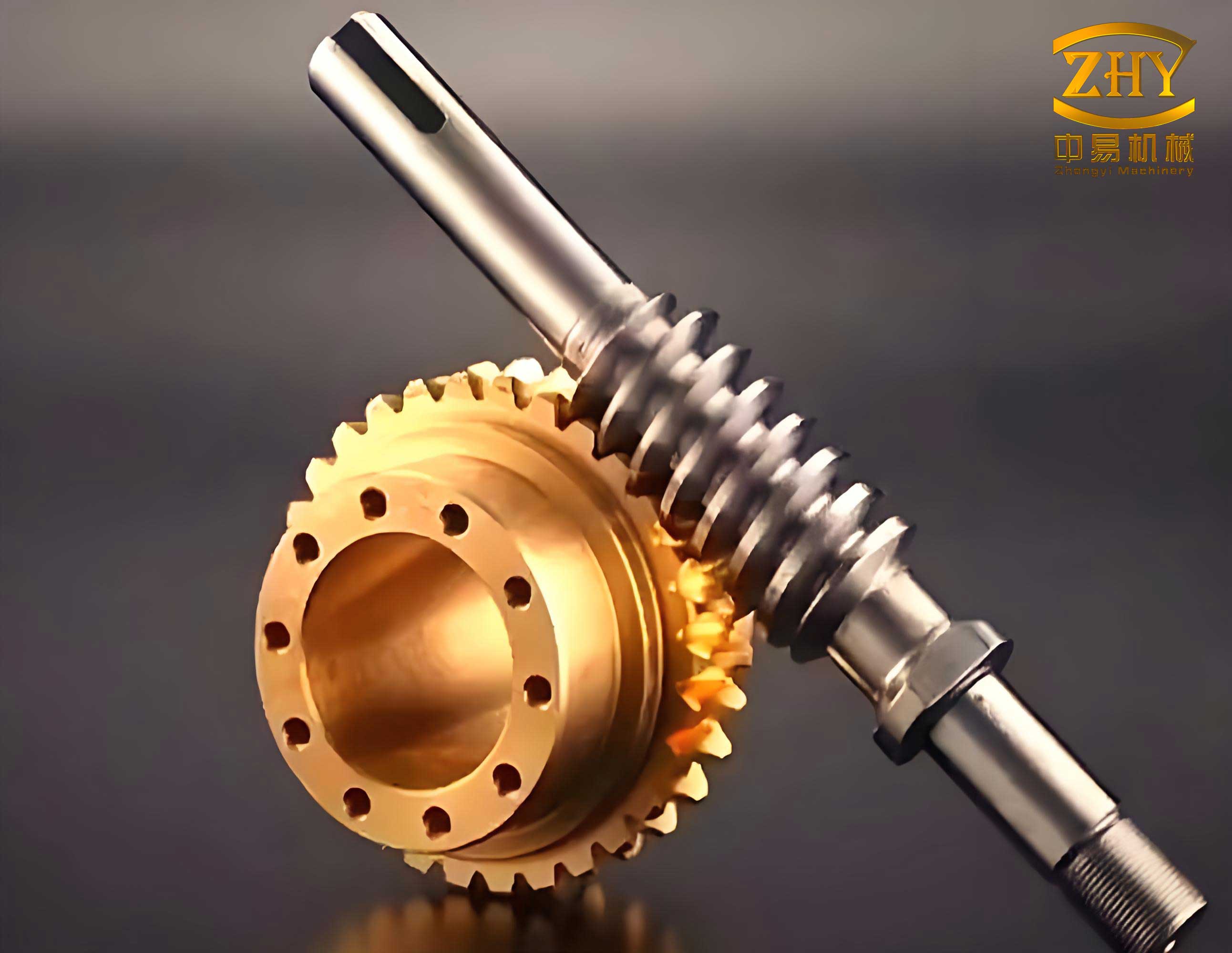
1. Mathematical Foundation and Meshing Principle
1.1 Coordinate System Establishment
The kinematic and geometric analysis of the planar enveloping internal meshing screw gears necessitates a precise coordinate framework. Multiple coordinate systems are defined to describe the relative motion and surface generation between the worm and the internal gear (worm wheel).
- Fixed Frames: $$S_1 (O_1 – \mathbf{i}_1, \mathbf{j}_1, \mathbf{k}_1)$$ is fixed to the worm housing, and $$S_2 (O_2 – \mathbf{i}_2, \mathbf{j}_2, \mathbf{k}_2)$$ is fixed to the gear housing.
- Moving Frames: $$S_{1′} (O_{1′} – \mathbf{i}_{1′}, \mathbf{j}_{1′}, \mathbf{k}_{1′})$$ is attached to and rotates with the worm at angular velocity $$\omega_{1′}$$ about its axis $$\mathbf{k}_{1′}$$. $$S_{2′} (O_{2′} – \mathbf{i}_{2′}, \mathbf{j}_{2′}, \mathbf{k}_{2′})$$ is attached to and rotates with the internal gear at angular velocity $$\omega_{2′}$$ about its axis $$\mathbf{k}_{2′}$$.
- Generating Plane Frame: $$S_0 (O_0 – \mathbf{i}_0, \mathbf{j}_0, \mathbf{k}_0)$$ is associated with the generating plane $$\Sigma$$. The $$\mathbf{j}_0$$ and $$\mathbf{k}_0$$ axes lie within this plane. The origin $$O_0$$ is located on the base circle, with its position in $$S_{2′}$$ given by $$\mathbf{r}_0 = (0, r, 0)^T$$, where $$r$$ is the base circle radius.
- Contact Point Frame: At the instantaneous contact point $$P$$, a local frame $$S_P (O_P – \mathbf{e}_1, \mathbf{e}_2, \mathbf{e}_3)$$ is set, where $$\mathbf{e}_1 \parallel \mathbf{k}_0$$ and $$\mathbf{e}_2 \parallel \mathbf{j}_0$$, both lying on plane $$\Sigma$$. The coordinates of $$P$$ in $$S_0$$ are $$\mathbf{r}_p = (0, u, v)^T$$.
The primary geometric parameters are: the number of worm threads $$z_1$$, the number of gear teeth $$z_2$$, the generating plane inclination angle $$\beta$$, the center distance $$A$$, and the installation angle (gear tilt) $$\delta_F$$. The transmission ratio during the generation process is $$i_c = z_1 / z_2$$. The angular displacements at a given instant are $$\varphi_1$$ for the worm and $$\varphi_2 = i_c \varphi_1$$ for the gear.
The fundamental vector relationship between the coordinate origins and the contact point is: $$\mathbf{r}_{2′} = \boldsymbol{\xi} + \mathbf{r}_{1′}$$, where $$\boldsymbol{\xi}$$ is the center distance vector.
Based on the theory of gearing, the coordinate transformation matrices are critical. The transformation from the gear’s moving frame $$S_{2′}$$ to the worm’s moving frame $$S_{1′}$$ is given by the matrix $$\mathbf{M}_{2’1′}$$:
$$\mathbf{M}_{2’1′} = \begin{bmatrix}
p_1 + l_2 p_2 & l_2 p_4 – p_3 & -l_1 g_2 & A g_1 \\
l_2 p_3 – p_4 & p_2 + l_2 p_1 & -l_1 g_1 & -A g_2 \\
l_1 h_2 & l_1 h_1 & l_2 & 0 \\
0 & 0 & 0 & 1
\end{bmatrix}$$
where $$g_1 = \cos \varphi_1, g_2 = \sin \varphi_1, h_1 = \cos \varphi_2, h_2 = \sin \varphi_2, l_1 = \cos \delta_F, l_2 = \sin \delta_F, p_1 = g_1 h_1, p_2 = g_2 h_2, p_3 = g_1 h_2, p_4 = g_2 h_1$$.
The transformation from the generating plane/contact point frame $$S_0$$ to the gear’s moving frame $$S_{2′}$$ is:
$$\mathbf{M}_{02′} = \begin{bmatrix}
0 & 1 & 0 & 0 \\
-\cos \beta & 0 & -\sin \beta & r \\
-\sin \beta & 0 & \cos \beta & 0 \\
0 & 0 & 0 & 1
\end{bmatrix}$$
1.2 Meshing Equation
The necessary condition for proper conjugate meshing between the screw gear surfaces is that the common normal vector at the contact point is perpendicular to the relative velocity vector of the two surfaces at that point. This leads to the meshing equation:
$$\Phi = \mathbf{v}_{1’2′}^{(0)} \cdot \mathbf{i}_0 = 0$$
where $$\mathbf{v}_{1’2′}^{(0)}$$ is the relative velocity vector expressed in the $$S_0$$ frame. Its components are derived as:
$$
\begin{aligned}
x_0^v &= \sin \beta [\cos \delta_F \cos \varphi_2 (u + A \cos \varphi_2) + \cos \delta_F \sin \varphi_2 (A \sin \varphi_2 – r + v \sin \beta)] \\
&+ \cos \beta [(u + A \cos \varphi_2)(i_c – \sin \delta_F) – A i_c \cos \varphi_2 + v \cos \beta \cos \delta_F \sin \varphi_2] \\
y_0^v &= A i_c \sin \varphi_2 – (i_c – \sin \delta_F)(A \sin \varphi_2 – r + v \sin \beta) + v \cos \beta \cos \delta_F \cos \varphi_2 \\
z_0^v &= \sin \beta [(u + A \cos \varphi_2)(i_c – \sin \delta_F) – A i_c \cos \varphi_2 + v \cos \beta \cos \delta_F \sin \varphi_2] \\
&- \cos \beta [\cos \delta_F \cos \varphi_2 (u + A \cos \varphi_2) + \cos \delta_F \sin \varphi_2 (A \sin \varphi_2 – r + v \sin \beta)]
\end{aligned}
$$
Solving the meshing equation $$\Phi=0$$ for $$v$$ yields:
$$v = \frac{B_1}{B_2}$$
where
$$
\begin{aligned}
B_1 &= u \cos \beta \sin \delta_F + A \cos \beta \cos \varphi_2 \sin \delta_F – u \cos \varphi_2 \cos \delta_F \sin \beta – i_c u \cos \beta \\
&+ r \cos \delta_F \sin \beta \sin \varphi_2 – A \cos \delta_F \sin \beta \\
B_2 &= \cos \delta_F \sin \varphi_2 \quad (\varphi_2 \neq 0)
\end{aligned}
$$
1.3 Tooth Surface Equation
The locus of contact points during meshing defines the tooth surfaces of both the internal worm and the gear. The family of contact lines generates these surfaces. The parametric equations for the worm surface (in $$S_{1′}$$) and the gear surface (in $$S_{2′}$$) are:
$$
\begin{aligned}
[\mathbf{r}_{1′}, 1]^T &= \mathbf{M}_{2’1′} \cdot \mathbf{M}_{02′} \cdot [\mathbf{r}_p, 1]^T \\
[\mathbf{r}_{2′}, 1]^T &= \mathbf{M}_{02′} \cdot [\mathbf{r}_p, 1]^T \\
\text{subject to: } & v = B_1/B_2, \quad u = \text{constant}, \quad \varphi_2 = i_c \varphi_1
\end{aligned}
$$
By varying the parameter $$u$$ along the contact line and the motion parameter $$\varphi_1$$, the complete tooth surfaces of these advanced screw gears can be constructed. The unique geometry of the internal meshing worm allows it to engage with multiple gear sectors, enabling the desired multi-output capability from a single driving screw gear.
1.4 Induced Normal Curvature
A key indicator of the contact conditions and stress state between mating gear teeth is the induced normal curvature. For a pair of screw gears, it quantifies the relative curvature of the two surfaces along the contact normal direction. A lower induced normal curvature generally corresponds to lower contact stresses and better load distribution, which are critical for the durability and performance of screw gears.
The formula for the induced normal curvature $$k_{1’2′}$$ along the relative velocity direction is derived from differential geometry and gear meshing theory:
$$k_{1’2′} = \frac{(\boldsymbol{\omega}_{1’2′}^{(0)} \times \mathbf{i}_0 – \mathbf{v}_{1’2′}^{(0)} \cdot \frac{d\mathbf{i}_0}{ds})^{(2)}}{\Psi}$$
The first-order function $$\Psi$$ in the denominator is:
$$\Psi = \frac{d\Phi}{dt} + (\boldsymbol{\omega}_{1’2′}^{(0)}, \mathbf{i}_0, \mathbf{v}_{1’2′}^{(0)})$$
where $$\boldsymbol{\omega}_{1’2′}^{(0)}$$ is the relative angular velocity vector in $$S_0$$, with components:
$$
\begin{aligned}
x_0^{\omega} &= \sin \beta (i_c – \sin \delta_F) – \cos \beta \cos \delta_F \cos \varphi_2 \\
y_0^{\omega} &= \cos \delta_F \sin \varphi_2 \\
z_0^{\omega} &= -\cos \beta (i_c – \sin \delta_F) – \cos \delta_F \cos \varphi_2 \sin \beta
\end{aligned}
$$
The induced normal curvature is a direct input into the Hertzian contact stress model, establishing a direct link between geometry (influenced by $$\beta$$) and mechanical performance:
$$\sigma_H = \sqrt{ \frac{F_n E_1 E_2 k_{1’2′}}{l [E_1(1-\mu_2^2) + E_2(1-\mu_1^2)] } }$$
where $$F_n$$ is the normal load, $$l$$ is the contact length, $$E$$ and $$\mu$$ are material elastic moduli and Poisson’s ratios, respectively. This relationship underscores the importance of minimizing $$k_{1’2′}$$ to enhance the load capacity of the screw gear pair.
2. Influence of the Generating Plane Inclination Angle
The generating plane inclination angle $$\beta$$ is a master parameter in the design of planar enveloping screw gears. It controls the orientation of the tool plane that generates the worm, thereby affecting the worm thread geometry, the contact pattern, and critically, the induced normal curvature across the tooth surfaces of the mating screw gears.
2.1 Analysis Position and Parameter Influence
To systematically study the effect of $$\beta$$, a baseline configuration is first established: center distance $$A = 80 \text{ mm}$$, single-start worm ($$z_1=1$$), gear teeth $$z_2=40$$, installation angle $$\delta_F = 35^\circ$$, base radius $$r = 23 \text{ mm}$$. The parameter $$u$$, which spans the active face width of the gear tooth, varies between its root ($$u_{min}$$) and tip ($$u_{max}$$) values, calculated from the gear’s root and tip diameters.
For a fixed rotation angle, calculating $$k_{1’2′}$$ along the contact line (varying $$u$$) reveals the stress distribution tendency across the gear tooth flank of the screw gears. The results consistently show that the induced normal curvature is highest near the gear tooth root and decreases almost linearly towards the tooth tip. According to the Hertz formula, this leads to a non-uniform contact stress distribution, with the maximum stress occurring at the root region of the gear tooth (conversely, at the tip region of the worm thread in these internal meshing screw gears). This pattern aligns with finite element analysis results for similar gear contacts, confirming the root as the most critically loaded zone. Therefore, analyzing the influence of $$\beta$$ at a representative point near the gear tooth root ($$u = u_{min}$$) provides vital insights for optimizing the design of these screw gears against contact fatigue.
2.2 Effect of Gear Tooth Number Variation
We now investigate how the optimal $$\beta$$ changes with different gear tooth counts $$z_2$$, which alters the transmission ratio $$i_c$$. Holding other parameters constant ($$A=80 \text{ mm}, \delta_F=35^\circ, r=23 \text{ mm}, u=u_{min}$$), we calculate the induced normal curvature $$k_{1’2′}$$ as a function of $$\beta$$ (from $$0^\circ$$ to $$90^\circ$$) for various gear rotation angles $$\varphi_2$$ and different $$z_2$$.
The analysis reveals a consistent trend: while for small rotation angles the beneficial range of $$\beta$$ appears broad, as $$\varphi_2$$ increases, a distinct optimal zone emerges. Specifically, for a wide range of gear tooth numbers (e.g., $$z_2 = 30, 40, 50, 60$$), the induced normal curvature reaches its minimum—indicating best potential contact conditions for the screw gears—when the generating plane inclination angle $$\beta$$ lies within the approximate range of $$18^\circ$$ to $$36^\circ$$. Outside this range, $$k_{1’2′}$$ increases significantly, suggesting higher contact stresses and potentially poorer meshing performance for the screw gear pair.
The following table summarizes the observed trend for the induced normal curvature with varying $$z_2$$ and fixed $$\beta$$ ranges:
| Gear Tooth Count (z₂) | Transmission Ratio (i_c=z₁/z₂) | Induced Curvature Trend for β in 0°-18° | Induced Curvature Trend for β in 18°-36° | Induced Curvature Trend for β > 36° |
|---|---|---|---|---|
| 30 | 1/30 | Moderate to High | Minimum & Stable | High & Increasing |
| 40 | 1/40 | Moderate to High | Minimum & Stable | High & Increasing |
| 50 | 1/50 | Moderate to High | Minimum & Stable | High & Increasing |
| 60 | 1/60 | Moderate to High | Minimum & Stable | High & Increasing |
This indicates that the beneficial effect of the 18°-36° range is robust across different gear ratios for these single-start screw gears.
2.3 Effect of Center Distance Variation
To further generalize the finding, we examine the influence of the center distance $$A$$. Keeping $$z_2=40$$ and other parameters from the baseline constant, we analyze $$k_{1’2′}$$ versus $$\beta$$ for different center distances (e.g., $$A = 70, 80, 90, 100 \text{ mm}$$).
The results corroborate the earlier observation. Regardless of the change in center distance—a fundamental scaling parameter for screw gears—the induced normal curvature consistently finds its most favorable (lowest) values within the same $$\beta$$ band of approximately $$18^\circ$$ to $$36^\circ$$. For angles smaller than this range, the curvature values are suboptimal. For angles larger than $$36^\circ$$, the curvature rises sharply, which would be detrimental to the contact fatigue life of the screw gears. A detailed plot focusing on the 18°-36° range confirms that within this interval, the variation of $$k_{1’2′}$$ with $$\beta$$ is relatively flat and low, providing a stable, high-performance design window for the planar enveloping internal meshing screw gears.
The consistency of this result across varying key design parameters ($$z_2$$ and $$A$$) strongly suggests a fundamental geometric relationship. It implies that for the planar enveloping internal meshing screw gear configuration, orienting the generating plane within this specific angular window promotes a conjugate action that minimizes the relative curvature of the contacting tooth flanks. This minimization is a direct contributor to reducing Hertzian contact stress, improving lubrication conditions, and enhancing the overall load-carrying capacity and durability of the screw gear transmission system.
3. Discussion and Design Implications
The comprehensive numerical investigation leads to several conclusive points and practical guidelines for designers of these advanced screw gears:
1. Optimal Generating Plane Inclination: For single-start planar enveloping internal meshing screw gears, selecting a generating plane inclination angle ($$\beta$$) within the range of **18° to 36°** is highly recommended. This range reliably corresponds to lower induced normal curvature across a wide spectrum of design parameters, including gear tooth number and center distance. This lower curvature directly translates to the potential for lower contact stresses and improved meshing performance, which are critical metrics for the reliability of screw gears.
2. Contact Stress Distribution: The analysis confirms that, like many other worm gear types, the contact stress in these screw gears is not uniformly distributed across the tooth flank. The induced curvature, and consequently the contact stress, is highest near the root of the gear tooth (tip of the worm thread). This identifies the root region as the critical zone for contact fatigue failure, which must be carefully considered during the strength design and material selection for the screw gears.
3. Foundation for Multi-parameter Optimization: Establishing this optimal range for $$\beta$$ simplifies the complex multi-parameter optimization process for designing planar enveloping internal meshing screw gears. It allows designers to fix this parameter within a proven beneficial interval early in the design process, reducing the dimensionality of the optimization problem and focusing computational resources on fine-tuning other parameters such as the installation angle $$\delta_F$$, profile modifications, and lubrication design specifically for these screw gears.
4. Path for Further Research: While this study focuses on the influence of $$\beta$$ under varying $$z_2$$ and $$A$$, future work should investigate the interaction of the generating plane inclination angle with other critical parameters, such as the installation angle $$\delta_F$$ and the number of worm starts $$z_1$$ (multi-start screw gears). Furthermore, exploring the impact of $$\beta$$ on other performance indicators like transmission efficiency, sensitivity to misalignment, and thermal behavior will provide a more holistic understanding of these innovative screw gear systems.
4. Conclusion
This in-depth analysis of the planar enveloping internal meshing screw gear transmission has systematically elucidated the profound influence of the generating plane inclination angle on its fundamental meshing characteristics. By developing the mathematical model based on gear meshing theory and employing numerical analysis of the induced normal curvature, a key proxy for contact stress, we have identified a robust design rule. For single-start configurations, setting the generating plane inclination angle within the range of 18° to 36° consistently yields superior meshing conditions characterized by minimized relative curvature. This finding provides a vital theoretical foundation and a practical design guideline for optimizing the performance, load capacity, and durability of this novel and promising class of screw gears, paving the way for their more effective application in advanced mechanical systems requiring compact, high-torque, and multi-output transmission solutions.