1. Determination of Special Operating Points for Exciter Helical Gear Transmission
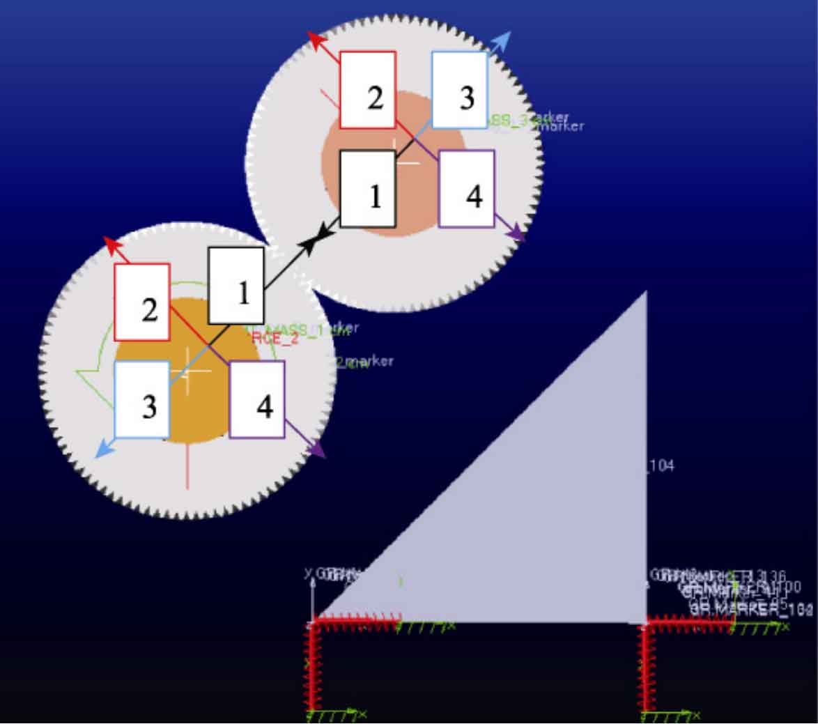
The exciter helical gear pair typically performs three types of motion: high-speed rotational motion around the shaft, reciprocating motion under alternating loads, and relative motion along the centerline of the helical gear under the combined action of eccentric block centrifugal force and large bearing clearance. The loads it bears include: driving the speed of the driving wheel, applying load torque to the driven wheel, inertia force and gravity generated by the reciprocating motion of the helical gear. The four special deflection angles of the eccentric blocks on the main and driven shafts shown in Figure 1 are defined as 0 °, 90 °, 180 °, and 270 °, respectively, for positions 1, 2, 3, and 4.
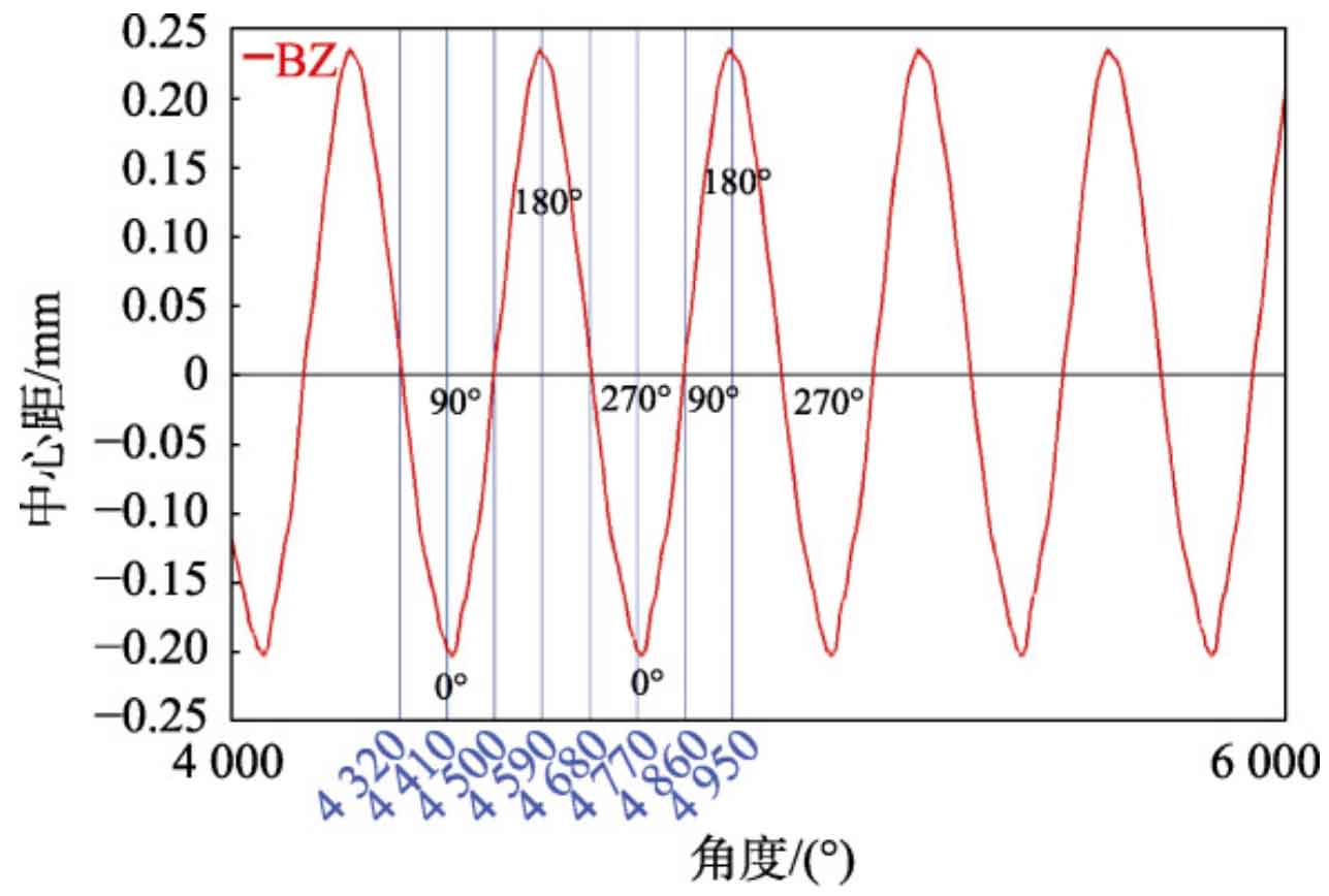
Under the combined action of internal and external excitation, the actual centers of the two helical gears of the exciter undergo periodic fluctuations. Figure 2 shows the difference between the actual center distance and the theoretical center distance, where a positive value indicates that the center distance of the helical gear is greater than the theoretical center distance, and a negative value indicates that the center distance of the helical gear is smaller than the theoretical center distance. During a rotation cycle, the maximum fluctuation in the center distance of the helical gear during operation from 270 ° (position 4) to 90 ° (position 2) is -0.194 mm; The maximum fluctuation in the center distance of the helical gear during operation from 90 ° (position 2) to 270 ° (position 4) is 0.234 mm. Without considering the torque fluctuation during the meshing process of the helical gear, the average load torque of the exciter helical gear during operation is simulated and shown in Table 1. Static analysis of the helical gear pairs under various working conditions in the table can explore the dangerous working conditions of the exciter helical gear pairs.
| Deviation angle/(°) | Gravitational acceleration gy/mm · s ^ -2 | Gravitational acceleration gx/mm · s ^ -2 | Inertial force acceleration/mm · s ^ -2 | Load torque/N · mm | Individual gear displacement on centerline/mm |
| 0 | –8 338.85 | –8 338.85 | 0.00 | 2.337E+5 | 0.097 |
| 90 | –8 338.85 | –8 338.85 | 16 038.11 | 2.337E+5 | 0.00 |
| 180 | –8 338.85 | –8 338.85 | 0.00 | 2.337E+5 | 0.117 |
| 270 | –8 338.85 | –8 338.85 | –16 038.11 | 2.337E+5 | 0.00 |
2. Determination of hazardous working conditions for exciter helical gear pairs
To speed up the calculation speed and accuracy, the helical gear pair is simplified into 8 or more meshing models, and mesh is divided in HyperMesh. The mesh size of the contact area is at least 1/10 of the Hertz contact half width.
Figure 3 shows the simulation calculation results of the contact stress of the helical gear pair at a deviation angle of 0 °. There are 8 pairs of teeth involved in meshing in the figure, which is consistent with the total overlap of the helical gear calculated under normal operating conditions of 7.08. During operation, due to the decrease in the center distance of the helical gear and being smaller than the theoretical center distance, a phenomenon of “tooth squeezing” occurs, where both sides of the gear teeth participate in meshing simultaneously and there is contact stress. The maximum contact stress area is in the middle of the helical gear contact line, which is 802.9 MPa.
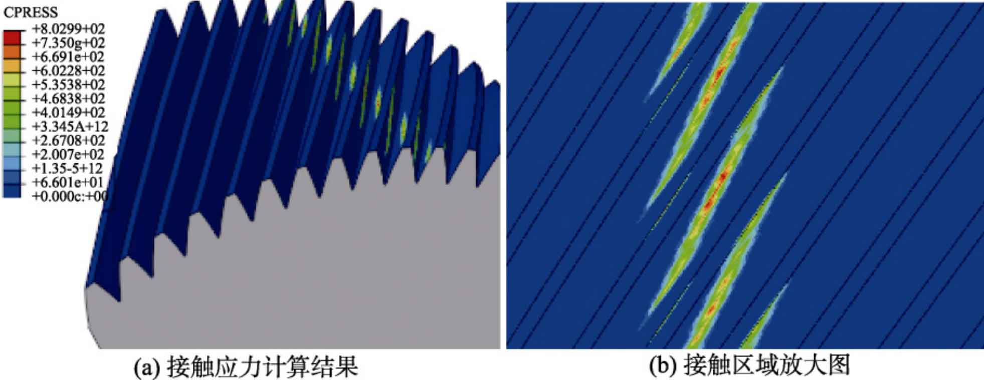
Figure 4 shows the simulation calculation result with a deviation angle of 90 °. At this time, there is no relative displacement of the helical gear pair in the centerline direction, and the initial installation center distance is maintained. Compared to the situation at 0 °, the equivalent stress and contact stress of the gear are greatly reduced at 90 °, and it is a single-sided contact. The maximum contact stress is located at the tooth tip, which is caused by the omission of the chamfer at the tooth tip of the helical gear and the concentration of stress. Due to the fact that the stress cloud maps of the other two rotation angles are not significantly different from those at 90 °, they will not be displayed anymore.
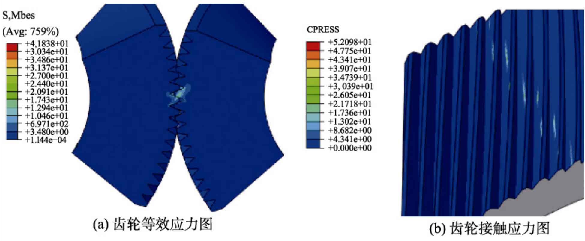
Table 2 shows the maximum equivalent stress and contact stress of helical gears at various deflection angles. It can be seen that the inertia force and the increase in center distance of the helical gear have little effect on the stress value and stress distribution. When the deflection angles are 90 °, 180 °, and 270 °, the stress situation of the helical gear is much smaller than the strength limit of the material. When the deflection angle is 0 °, the reduction of the center distance of the helical gear causes tooth extrusion, resulting in a sharp increase in the maximum contact stress and equivalent stress of the helical gear. Although the simulation calculation results under this working condition are slightly lower than the material strength limit of 1100 MPa, long-term operation will inevitably cause fatigue damage to the helical gear. Therefore, it is determined that this angle position is a dangerous working condition point, and it is necessary to conduct fatigue analysis on the helical gear pair under this working condition.
| Deviation angle/(0 °) | Deviation angle/(90 °) | Deviation angle/(180 °) | Deviation angle/(270 °) | |
| Maximum contact stress/MPa | 802.90 | 52.09 | 49.37 | 49.79 |
| Maximum equivalent stress/MPa | 792.30 | 41.83 | 41.34 | 39.95 |
3. Fatigue life analysis under standard center distance
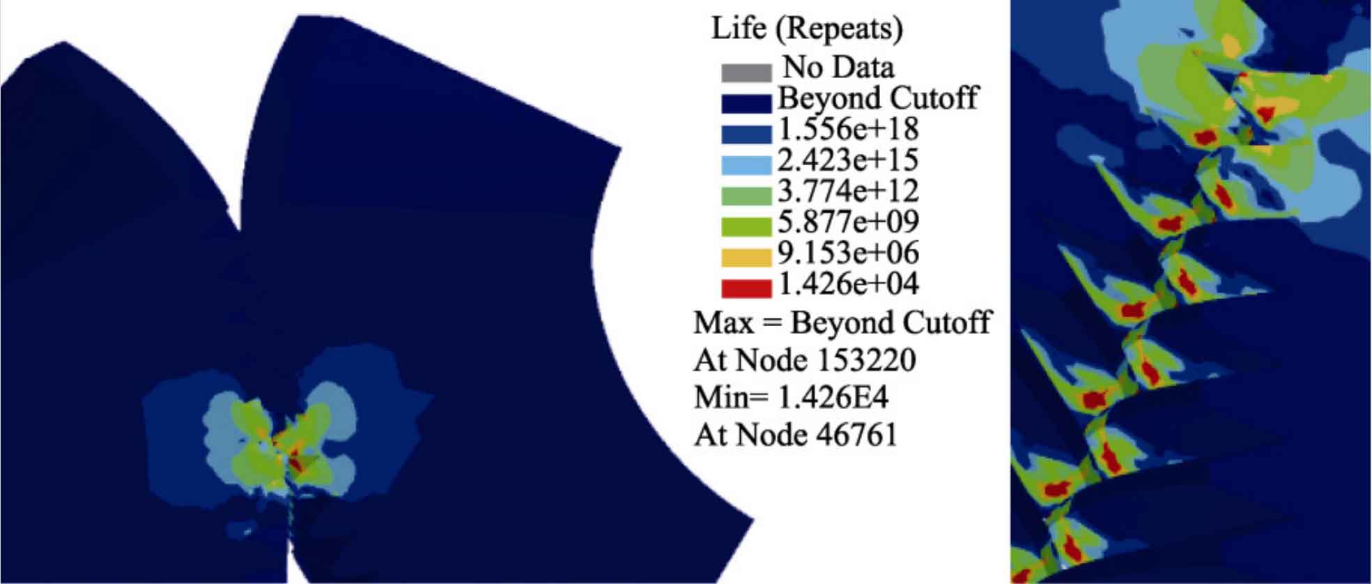
Import the static calculation results of the helical gear under the dangerous working condition with a deviation angle of 0 ° into NCode software, define the material mapping to introduce the S-N curve of the helical gear material 20GrMnTi, and use the final equivalent stress calculated from the static analysis as the cyclic input. Apply cyclic symmetric loads with maximum and minimum coefficients of 1 and -1, respectively, to the cyclic input results, Finally, the fatigue life of the exciter helical gear was calculated, as shown in Figure 5. It can be seen that the locations where damage is prone to occur are the contact position and tooth root position of the helical gear meshing, which is consistent with the common faults of helical gears in actual production. The fatigue life of the severely damaged location is lower than the infinite fatigue life standard cycle 106 in NCode, indicating that the exciter helical gear is highly likely to experience fatigue failure. Through simulation analysis, it was further verified that the main reason for the failure of the helical gear pair in the vibrating screen exciter is the periodic tooth squeezing caused by the actual center distance of the helical gear pair being smaller than the theoretical center distance. If the tooth squeezing effect can be reduced, the service life of the helical gear can be improved.
The periodic dynamic fluctuation of the actual center distance of helical gears is caused by the combined action of eccentric block centrifugal force and large bearing clearance. In actual production, the use of large clearance bearings is to avoid frequent faults such as high temperature and internal parts jamming in the bearings. Therefore, the bearing clearance cannot be reduced arbitrarily. In view of this, this article focuses on studying the appropriate way to increase the center distance.
4. Fatigue life analysis under non-standard center distance
If the installation center distance of the helical gear is greater than the theoretical center distance, it will inevitably introduce tooth side clearance (backlash) during the meshing process of the helical gear. The backlash should be maintained within a suitable range. Excessive backlash can affect the transmission accuracy of the helical gear and may also cause the helical gear to vibrate, resulting in strong impact during gear meshing. In fact, during the installation process of helical gears, in order to prevent thermal expansion of the helical gear mesh, a certain amount of tooth side clearance is reserved. For ordinary rotating mechanical helical gears, there is an optimal normal tooth side clearance, and its calculation formula is:
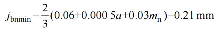
For the exciter helical gear pair, in a virtual prototype model that cannot consider actual tooth difference, in order to ensure the rationality of introducing non-standard center distance and take into account the impact of increasing center distance on tooth side clearance, the optimal value of 0.21 mm for calculating tooth side clearance is used as the modified center distance side clearance value. Then, based on the relationship between the helical gear side clearance and the installation center distance (see formula), the actual installation center distance of the helical gear is calculated in reverse:
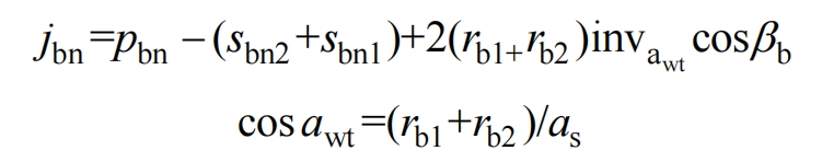
In the formula: jbn is the normal clearance of the helical gear; PBN is the normal tooth pitch of the base circle; The tooth thickness of the base normal surface of the main and driven gears for sbn1 and sbn2, respectively; Rb1 and rb2 respectively have the base radius of the main and driven gears; Wt a is the actual pressure angle of the helical gear; β B is the base helix angle of the helical gear; As is the actual installation center distance of the helical gear.
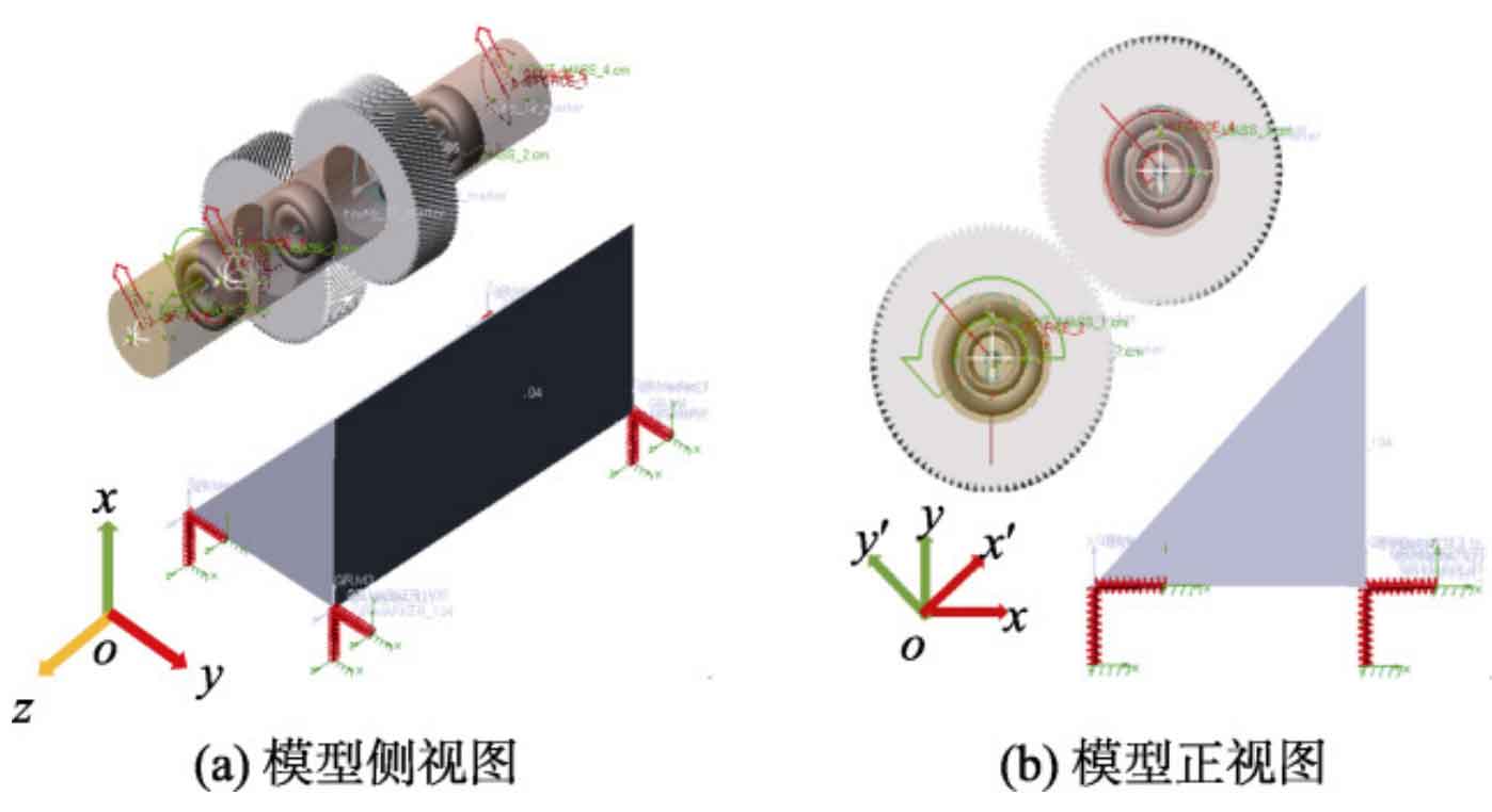
After substituting the parameters, the actual installation center distance as of the helical gear is 330.308 1 mm, with a difference of 0.305 7 mm from the theoretical center distance. In the model shown in Figure 6, by modifying the position of the relevant components, a virtual prototype model of the non-standard center distance installation exciter can be obtained. Figure 7 shows the helical gear meshing model after changing the installation center distance.
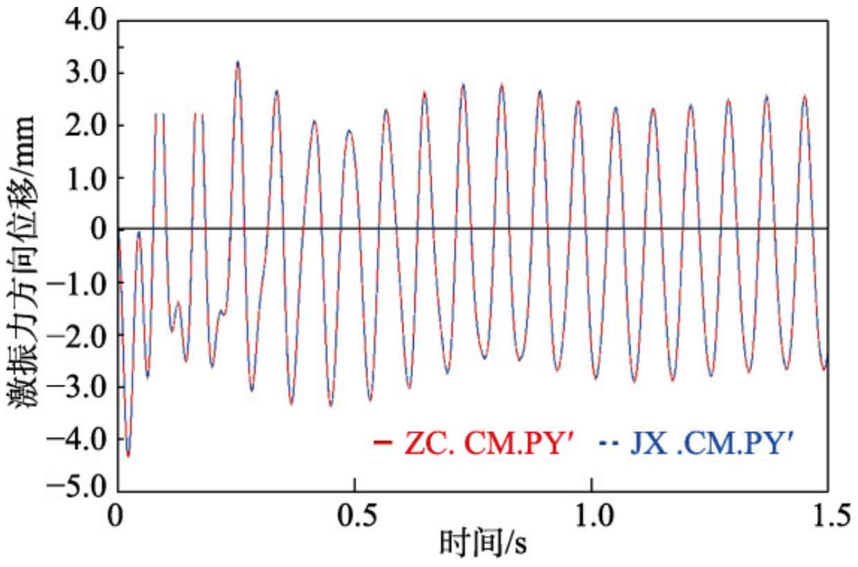
Figure 8 shows the displacement curves of the vibrating screen in the direction of the excitation force at non-standard center distance (x ‘, y’) (blue) and standard center distance (x ‘, y’) (red), respectively. The two curves basically overlap, indicating that the change in the center distance of the helical gear installation did not affect the vibration trajectory required for the vibrating screen.
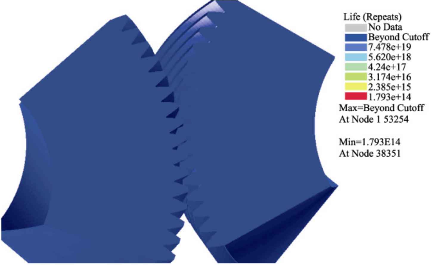
Repeat the previous process and perform fatigue life analysis on the helical gear pair installed with non-standard center distance, as shown in Figure 9. It can be seen that there is no obvious damage area, and the minimum lifespan of the helical gear is 1.79E+14, which is far greater than the requirements of the infinite lifespan design of the helical gear. This indicates that the plan of appropriately increasing the center distance of the helical gear to extend its lifespan is reasonable and effective.