
0 Introduction
Gear transmission is a kind of mechanical transmission that is widely used, which has the characteristics of high transmission accuracy, wide transmission power range, reliable operation, long service life, high transmission efficiency, parallel shaft transmission, staggered shaft transmission, etc. There are two working modes of gear transmission: one is used to transmit force and torque, such as various types of reducers; Another type of transmission motion, such as the gear transmission of measuring instruments, the indexing gear transmission of machine tools, the position feedback mechanism in the control system, etc. The transmission accuracy of gears mainly refers to the accuracy of gear transmission. Due to the storage of parts of the gear transmission device (including gears, shafts, bearings, etc.).
Temperatures can also occur during manufacturing and assembly errors, as well as during transmission
degree of deformation and force elastic deformation, etc., so the output shaft in the transmission process
There will always be errors in the corners. For gearing, this kind of mistake
The difference is mainly transmission error and idle stroke. As the position feedback mechanism of the transmitter, the transmitter receiver generally feeds back the angle of the equipment to the control equipment through the small module gear transmission. Due to the system requirements, the transmission accuracy of the signal receiver is high, so it is necessary to predict the transmission accuracy when designing the signal receiving instrument. For the accuracy of small module spur gear transmission, a lot of relevant research has been carried out in China. In the research process, the matching error between the gear hole and the shaft, the bearing runout error, the transmission error caused by the gear manufacturing error, the comprehensive transmission error of a single gear, and the error of the output shaft were considered, but the influence of the box shape and position tolerance on the accuracy of the transmission system was not considered. For the influence of the geometric tolerance of a single part on the size chain, domestic scholars have carried out relevant research on this topic, and the literature has put forward it Considering the assembly dimension chain calculation method of geometric tolerances (such as axiality and perpendicularity), and by using the extreme value method, it is calculated that the minimum fitting clearance is reduced when considering geometric tolerances, and the assembly accuracy is also reduced. In this paper, a tolerance dimension calculation method considering geometric and positional tolerances using Monte Carlo simulation method is proposed. In this paper, a new two-dimensional assembly tolerance analysis method for vector ring assembly model including almost all geometric feature variations is proposed, and an example is given to calculate the top column assembly with geometric tolerance, and it is concluded that considering the geometric tolerance and its influence, the tolerance of the closed ring increases. It can be concluded that in the small module gear transmission system, the design is if Without considering the box shape and position tolerance factors, the calculated value of transmission accuracy is obtained If the transmission accuracy of the design is not sufficient, the processing is completed The small module spur gear transmission mechanism may have the transmission accuracy not meet the system requirements.
1 The condition of considering the geometric tolerance in the precision analysis of small module gear transmission
The shape tolerance is the error between the shape of the actual geometric element on the part and the ideal shape, the position tolerance is the error between the actual geometric position of the part and the ideal position, and the shape error and position error are referred to as the shape tolerance. GB/T 1182-2018 divides geometric tolerances into four categories: shape tolerances, orientation tolerances, position tolerances and runout tolerances. The tolerance principle is divided into the principle of independence and the principle of relevance, which in turn can be divided into the principle of inclusion and the principle of maximum entity Rule. According to the tolerance principle adopted for the size and geometric tolerance of the part, the treatment method of the geometric tolerance in the transmission accuracy analysis is also different.
1.1 Parts designed according to the inclusion requirements
The inclusion requirement is a requirement that the actual element to be measured shall not exceed the maximum physical boundary everywhere, and the size element that adopts the inclusion requirement should be marked with the symbol “E” after its dimensional limit deviation or tolerance code. The essence of the inclusion requirement is to control the shape and position tolerance with the dimensional tolerance of the part, therefore, under the inclusion requirement, the shape and position tolerance of the box is included in the dimensional tolerance, which will not affect the accuracy of the transmission system of the small module gear, so the transmission is refined When calculating the degree, only need to consider the gear error, gear and shaft assembly error, etc. It is not necessary to include the geometric tolerances of the box.
1.2 Parts designed according to the principle of independence
Each of the dimensional and geometric (shape, orientation, or position) requirements given on the drawing is independent of each other and should meet its own requirements. In the actual specification of the product drawing, it is proposed that if there are no other standards or special labels, it means that the principle of independence is observed. Under the principle of independence, the size of the actual element is controlled by the dimensional tolerance, which has nothing to do with the geometric tolerance. Geometric tolerances are controlled by geometric tolerances and are independent of dimensional tolerances. Therefore, the transmission accuracy is calculated In addition to the dimensional tolerances such as gears, the corresponding geometric tolerances should also be considered.
2 Error of small module gear transmission system
2.1 Gear transmission system error
The concept of gear transmission error was proposed by Smith, a professor at the University of Cambridge in the United Kingdom, in the 70s of the 20th century: “the difference between the theoretical position and the actual position of the output gear under the condition that the drive is completely accurate and rigid”. The comprehensive transmission error of transmission is composed of return difference and transmission error. The transmission error of the transmission chain is the synthesis of the transmission error of each gear, and the transmission error of each gear is mainly made by the gear itself and the shaft, bearing and other parts where it is located Caused by errors in manufacturing and assembly. SJ 2557-1984 small module gradual The accuracy calculation method of open-line cylindrical gear transmission chain proposes a small module involute The formula for calculating the idle stroke of a cylindrical gear transmission chain takes into account the gear pair Mean idle stroke due to circumferential backlash, torsional elastic empty return stroke of gear pair, temperature
Degree change caused by circumferential backlash resulting in an idle stroke. In this paper, only the mean value of the idle distance caused by the circumferential backlash of the gear pair caused by the machining factors of the box is considered for analysis, and the circumferential backlash caused by the torsional elastic return and temperature change of the gear pair is not changed. Therefore, under the condition of torsional idle stroke and elastic idle stroke without considering the temperature, the gear unidirectional transmission error ∆φ see Eq. (1), the transmission return difference of the transmission pair ∆φ’ see Eq. (2), and the maximum return error Φ of the output shaft of the gear transmission system is shown in Equation (6).
2.2 The influence of geometric tolerance on the accuracy of small module gear transmission system
In the design of small module spur gear transmission system, the design of parts generally adopts the principle of independence, and in order to facilitate the control of the machining accuracy and assembly accuracy of the parts, the parallelism, coaxiality and circular runout and other shape-position tolerances of the shafting system are usually marked on the box design drawing. From the definition of geometric tolerance, it can be seen that the parallelism and coaxiality of the box affect the center distance of the gear pair assembly. The circular runout of the gearbox affects the circular runout of the gears. The following is a discussion and analysis.
2.2.1 The influence of the box parallelism tolerance on the center distance of the gear transmission
The shaft hole actually machined by the box may have two situations: the axis is parallel or the axis is not parallel. From the definition of geometric tolerance, it can be concluded that when the two axes are parallel, the parallelism tolerance has the greatest influence on the center distance, so the effect of parallelism on the center distance is analyzed in parallel with the two axes. There are two types of arrangement of the gear drive shaft system in the design: (1) one-dimensional arrangement, where the two gear centers in the gear pair have a difference in the abscissa in the horizontal direction (or height direction) and the ordinate is the same, or the two gear centers are in the height direction (or horizontal direction).There is a difference in the ordinate, and the abscissa is the same (Figure 1). (2) Two-dimensional arrangement, teeth The center of the two gears in the wheel pair has a difference in the abscissa in the horizontal direction (or height direction) (Fig. 2). In both cases, the box parallelism tolerance pairs The effects of center distance are discussed separately.
Fig.1. Gear shaft center arrangement (1D)
Fig.2. Gear shaft center arrangement (2D)
Suppose gear 1 is centered on O1, gear 2 is centered on O2, and gear 3 is centered on O3. When the gear sub-center is arranged in one dimension on the box (fig. 1), the effect of the box parallelism tolerance on the center distance of the gear drive is only an increase or decrease (fig. 3). From the relevant definition in GB/T 1182-2018, it can be seen that the parallelism tolerance is an asymmetric ring. Therefore, when analyzing according to the extreme value method, the parallelism tolerance should be calculated with the annotated value IT on the drawing. From Figure 1, it can be concluded that when the center of the gear shaft is in one dimension (X-axis square direction), the maximum tolerance for the increase in the secondary center distance of the gear due to the influence of parallelism is:

where ΔDX is the tolerance value of the parallelism of the gear pair on the box.
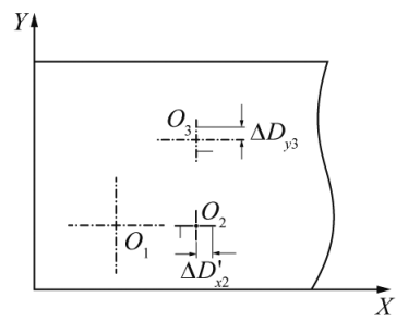
Fig.3 Parallelism affects the center of the axis Schematic diagram (1D)
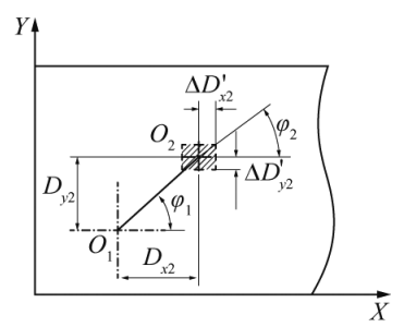
Fig.4. Parallelism affects the center of the axis Schematic diagram (2D)
When the gear sub-center is a two-dimensional arrangement on the box (Fig. 2).
The effect of box parallelism tolerance on the center distance of the gear drive is two-dimensional. hypothesis Gear 2 relative to gear 1 has a difference in the X direction Dx2 and the parallelism tolerance is
ΔD’x2, the difference between gear 2 and gear 1 in the Y direction is Dy2, parallelism
The tolerance is ΔD’y2, φ1 is the angle between the center distance and the X direction, and φ2 is flat because the box is flat The row tolerance results in an increased center distance with the angle in the X direction (Fig. 4). root According to the parallelism definition, it can be concluded that the center of the actual axis will be in the shaded area Domain. As you can see from the diagram, the actual center point is at the upper right vertex of the shaded part The center distance of the placement is the largest, and the equation (8) ~ (10) can be obtained.
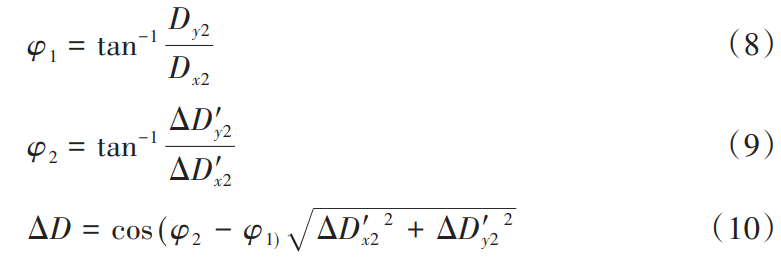
As can be seen from Eq. (7) and Eq. (10), when ΔD’x2=0 or ΔD’x2=0, the center layout of the gear shaft changes from a two-dimensional arrangement to a one-dimensional. Therefore, regardless of whether the center arrangement of the gear shaft is 1D or 2D, the tolerance for the increase in center distance due to parallelism can be calculated using equation (10).
2.2.2 The influence of the coaxiality tolerance of the box on the secondary center distance of the gear
From the definition of coaxiality, it can be known that the coaxiality of the box will cause the shaft to be not perpendicular to the plane of the box, which will eventually affect the center distance of the transmission system. Assuming that the width of the box is L and the width of the gear installation is L1, a schematic diagram of the box affecting the transmission center distance due to coaxiality can be obtained (Fig. 5). The tolerance of coaxiality is IT, which can be known from the relevant definition in GB/T 1182-2018: coaxiality and garden runout are symmetrical rings, therefore, the distance between the transmission center of the coaxiality is calculated The effect is half of the tolerance value. From Figure 5, it can be concluded that:
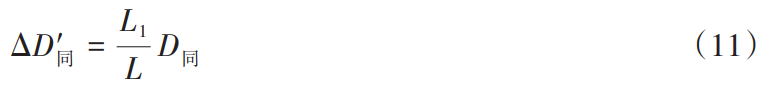
Where: the value of D is taken half of the coaxiality tolerance value of the box bearing bore; L
is the width of the box; L1 is the position of the gear installation; ΔD’ is coaxial due to the box
degree of deviation in the distance between the center of the installation.
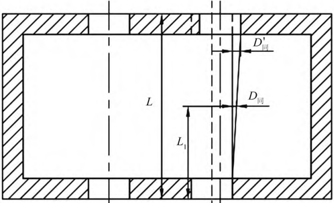
Fig.5. Schematic diagram of the influence of coaxiality on the distance between the transmission center
2.2.3 The influence of the circular runout tolerance of the box shaft bore on the center distance of the gear sub-center For shafts, the circular runout of the box directly affects the circular runout of the shaft. The effect on the runout of the shaft is very complex, and for the analysis using the extreme value method, it can be simply considered that the effect on the transmission center distance is directly additive. From the relevant definition in GB/T 1182-2018, it can be seen that the garden runout is a symmetrical ring, therefore, when calculating the influence of circular runout on the transmission center distance, Because half of the tolerance value is taken. Radial circular runout due to box runout tolerances
Actions:

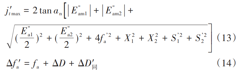
where: ST is half of the runout tolerance value of the box bearing borehole. In summary, when considering the box geometric tolerance, the formula for calculating j’t max should be Eq. (13).
3 Case Studies
The small module spur gear transmission system is meshed with the gear of the slewing mechanism by the gear Z0 of module 5 and the number of teeth of 18, and then the speed of the final gear Z4 is 1:1 after the deceleration of the two-stage small module spur gear. The electromechanical encoder is connected to the shaft III. by means of an elastic coupling When the slewing mechanism rotates, the electromechanical encoder feeds back the angle data to the control in real time
computer. The gearing center is arranged in a one-dimensional way, and the box bore is parallel
Degrees, circular runout, and concentricity tolerances are all 6 grades. Small module spur gear transmission The schematic diagram of the structure is shown in Figure 6, and the transmission parameter table is shown in Table 1.
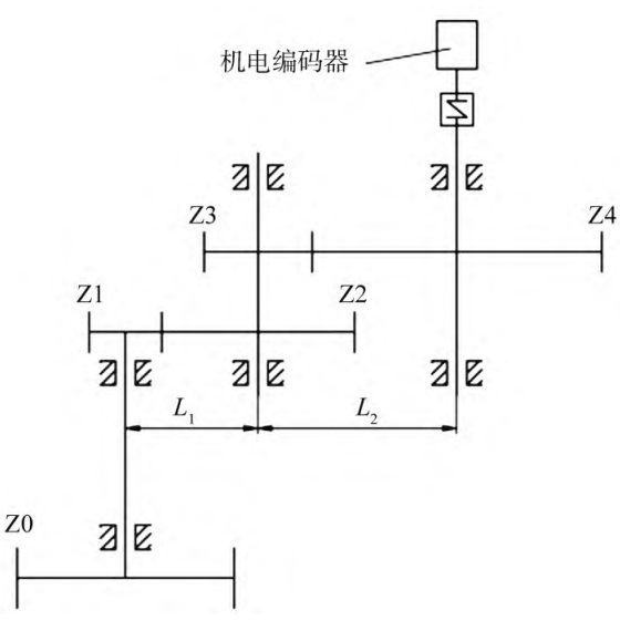
Fig.6. Transmission diagram of small module gear transmission system
In the design, the matching tolerance of the gear hole and the shaft is selected H7/h6 and H6/h5 respectively, the tolerance of the shaft center distance is selected with 7 levels of accuracy, the width of the box between the shaft I., shaft II and shaft III is 100 mm, and the gear installation is 50 from the inner wall GB10095 of the box. 1988 Transmission center distance limit deviation can be detected at different accuracy levels.
4 Concluding remarks
In this paper, the influence of box parallelism, coaxiality error and circular runout error on the accuracy of spur gear transmission system is studied, and through the analysis of the tolerance principle adopted by the geometric tolerance elements, it is concluded that the parallelism tolerance and coaxiality tolerance of the box will affect the center of the gear pair under the independent principle
distance, the circular runout of the box affects the circular runout of the gear, and the extreme value method calculation formula of the transmission accuracy of the small module gear with the shape and position tolerance under the principle of independence is proposed. Two different formulas were used to calculate the same drivetrain, and the difference in the calculation results was greater than 20%. Therefore, if the relevant calculation formula in SJ 2557-1984 is used to predict the transmission accuracy in the design, if the calculated transmission accuracy value is close to the design requirements, it is required in the final design Improve the accuracy of center distance, parallelism, concentricity, circular runout tolerance, etc Otherwise, the final transmission accuracy of the designed transmission system may not meet the requirements.