This article delves into the design and experimental research of non – circular gear – driven drag – type carrot harvesting devices. Aiming to address the issues of poor carrot root – stem separation and high damage rates in traditional harvesting devices, a novel design is proposed. Through theoretical analysis, structural design, simulation verification, and experimental testing, it comprehensively demonstrates the advantages of this new – type device, providing a valuable reference for the optimization of carrot harvesting machinery.
1. Introduction
Carrots are rich in nutrients and are widely cultivated around the world. China ranks among the top in carrot planting area and total output globally. The root – stem separation process in carrot harvesting is of utmost importance as it directly impacts the harvesting efficiency and the quality of the harvested carrots.
Traditional drag – type carrot harvesting devices, although featuring simple structures and high reliability, suffer from significant drawbacks. The constant – speed driving method often leads to poor root – stem separation results. The interaction between the drag rod and carrots easily causes scratches on the carrots, resulting in a high damage rate. Moreover, the separation is often incomplete, reducing the harvesting success rate.
Previous studies on improving the performance of drag – type carrot harvesting devices mainly focused on theoretical analysis of the working mechanism. For example, some researchers proposed mathematical models of carrots through simulation and experiments to reduce the damage rate, while others studied the mechanical properties of carrot tassels and put forward improved drag – rod speed curves. However, there is a lack of in – depth research and practical application verification on the motion characteristics of the drag rod in actual harvesting devices.
To overcome these limitations, this research focuses on the improvement of the drag – rod motion characteristics. By designing a non – circular gear – driven system, it aims to enhance the harvesting success rate, reduce the damage rate, and improve the overall performance of the drag – type carrot harvesting device.
2. Working Principle of Traditional Drag – type Carrot Harvesting Devices
The overall working process of the traditional drag – type carrot harvesting device involves several key steps. First, the buried carrots in the soil are loosened by the excavating component. Then, the conveyor belt grips the carrot tassels and moves them upward along the conveyor belt direction. When the carrots reach a specific position, two sets of drag rods in the drag device pull the carrots downward. Through the combined action of the drag rods and the conveyor belt, the root – stem separation of the carrots is achieved. This process is illustrated in Figure 1.
| Step | Action |
|---|---|
| 1 | Excavating component loosens carrots |
| 2 | Conveyor belt grips carrot tassels and moves upward |
| 3 | Drag rods pull carrots downward for root – stem separation |
2.2
The root – stem separation device is a crucial part of the drag – type carrot harvesting device. It mainly consists of components such as the drive gearbox, the active disc, the drag rod, the driven disc, and the support plate. As shown in Figure 2, during operation, the power device drives the active disc to rotate through the drive gearbox. The drag rod, inserted into the hinge holes of the active and driven discs, moves in a circular translational motion in the plane of the active disc. The two drag rods on the left and right sides have an overlapping area during movement, which is the working area of the drag rods. When the conveyor – belt – held carrot tassels enter this working area, the drag rods contact the carrot roots and generate a force along the z – axis direction. In cooperation with the conveyor belt, the carrot – pulling action is completed, achieving root – stem separation.
| Component | Function |
|---|---|
| Drive gearbox | Transmits power to drive the active disc |
| Active disc | Drives the drag rod to move in a circular translational motion |
| Drag rod | Pulls carrots for root – stem separation |
| Driven disc | Follows the movement of the drag rod |
| Support plate | Provides support for the structure |
3. Analysis of Drag – rod Motion Characteristics
The speed change of the drag rod in the traditional drag – type carrot root – stem separation device affects the interaction force between the drag rod and the carrots. When \(R = 50\) mm and \(\alpha=30^{\circ}\), the speed curve of the drag rod in the acting direction is a sine curve, as shown in Figure 3. During the actual working process, when the rotation angle of the active disc is between \(50^{\circ}\) and \(95^{\circ}\), the two opposite drag rods overlap or even cross each other, which is the working period of the drag rod. In this period, the speed of the drag rod increases from \(0.35\) m/s to the maximum speed of \(0.5\) m/s in a continuously accelerating state, with an acceleration that gradually decreases.
| Stage | Speed Change | Acceleration Change |
|---|---|---|
| Working period | Increases from 0.35 m/s to 0.5 m/s | Gradually decreases |
Research shows that the angle between the active disc and the drag rod, the radius of the circular translational motion of the drag rod, and the rotation speed of the disc all affect the motion characteristics of the drag rod acting on the carrots. In recent years, scholars have mainly focused on the impact of the structural parameters of the carrot harvester on the root – stem separation effect, ignoring the influence of the drag – rod motion characteristics. Through mechanical property tests on carrot tassels, it has been found that when the drag rod acts on the carrots at a high speed instantaneously, the root – stem separation effect is better. Based on this, an improved drag – rod speed curve is proposed, as shown in Figure 4. This curve is similar to a sine curve as a whole. In the first stage, the speed of the drag rod increases rapidly and evenly to the maximum point. In the second stage, it enters a stable high – speed working state with no speed increase. During the working stage, the drag rod can act on the carrots at a high speed instantaneously and continuously output force, which is beneficial to improving the root – stem separation effect. However, this conclusion has not been deeply studied and verified in actual carrot root – stem separation devices.
| Stage | Speed Change | Feature |
|---|---|---|
| First stage | Rapid and uniform acceleration to the maximum point | Build – up of high – speed state |
| Second stage | Stable high – speed state with no speed increase | Sustained high – speed action on c |
4. Design and Simulation of the New Root – Stem Separation Device
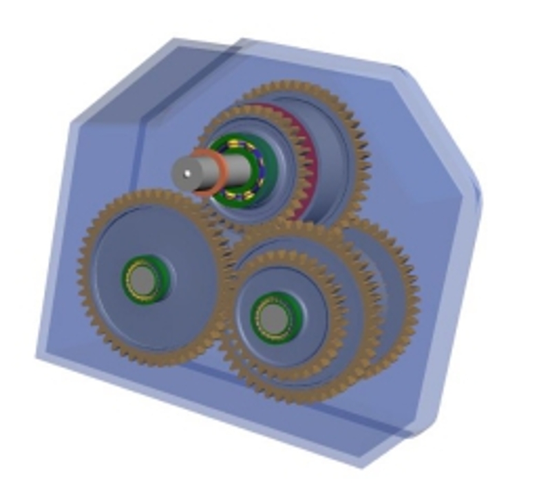
Non – circular gear pairs have flexible and variable transmission ratios, which can meet the diverse motion characteristic requirements of the drag – type carrot root – stem separation device. The non – circular gearbox, with non – circular gear pairs as the core, is a key component to achieve the improved motion characteristics of the drag rod. As shown in Figure 5, the non – circular gearbox includes non – circular gear pairs, reduction gear pairs, and constant – speed gear pairs. The power transmission route is as follows: power is transmitted from the active shaft through the non – circular gear pair to the reduction gear pair via the transmission shaft, and then through the constant – speed gear pair to the drag – rod drive disc through output shaft I and output shaft II.
| Component in Non – circular Gearbox | Function |
|---|---|
| Non – circular gear pairs | Provide variable transmission ratio for desired drag – rod motion |
| Reduction gear pairs | Adjust the speed and torque |
| Constant – speed gear pairs | Ensure stable output speed |
| Power transmission route | Active shaft → Non – circular gear pair → Transmission shaft → Reduction gear pair → Constant – speed gear pair → Output shaft I/II → Drag – rod drive disc |
The design of non – circular gear pairs adopts a reverse – design method based on the motion characteristics of the drag rod. First, a mathematical relationship is established between the improved drag – rod speed curve and the rotation angle of the active non – circular gear, as well as between the drag – rod speed curve and the rotation angle of the driven non – circular gear. Then, the transmission ratio of the non – circular gear is calculated. The mathematical relationships are as follows: \(V_{z}=f(\varphi_{1})\) \(V_{z}=\varphi_{2}’R\sin\varphi_{2}\) \(i = g(\varphi_{1})\) where \(\varphi_{1}\) is the rotation angle of the active non – circular gear, \(V_{z}\) is the improved drag – rod speed, \(\varphi_{2}\) is the rotation angle of the driven non – circular gear, and i is the transmission ratio of the non – circular gear.
4.2.2
Given the center distance of the gear pair and the calculated transmission ratio, the pitch curve of the non – circular gear can be calculated. The instantaneous transmission ratio of the non – circular gear pair is calculated by the formula \(i=\frac{\omega_{1}}{\omega_{2}}=\frac{r_{2}}{r_{1}}=\frac{a – r_{1}}{r_{1}}\) where a is the center distance of the non – circular gear pair, \(\omega_{1}\) and \(\omega_{2}\) are the instantaneous angular velocities of the active and driven non – circular gears respectively, and \(r_{1}\) and \(r_{2}\) are the distances from the instantaneous center P to the centers of the active and driven non – circular gears.
The pitch curve equation of the non – circular gear in the polar coordinate system is \(\left\{\begin{array}{l}r_{1}(\varphi_{1})=\frac{a}{1 + i}\\r_{2}(\varphi_{2})=a – r_{1}(\varphi_{1})=\frac{ai}{1 + i}\\\varphi_{2}=\int_{0}^{\varphi_{1}}\frac{1}{i}d\varphi_{1}\end{array}\right.\)
It should be noted that the pitch curve of the non – circular gear not only determines the transmission law of the gear but also affects the generation of the tooth profile and the difficulty of its manufacturing. Therefore, it is necessary to check the convexity and concavity of the pitch curve according to the radius of curvature of the pitch curve. The radius of curvature of the pitch curve is calculated by the formula \(\rho=\frac{\left[r^{2}+\left(\frac{dr}{d\varphi}\right)^{2}\right]^{\frac{3}{2}}}{r^{2}+2\left(\frac{dr}{d\varphi}\right)^{2}-r\frac{d^{2}r}{d\varphi^{2}}}\) where r is the radius of the gear pitch curve, and \(\varphi\) is the angle of the pitch – curve radius relative to the initial line. If \(\rho\) is positive, the gear pitch curve is convex, and the tooth profile can be generated smoothly without the need for optimization; otherwise, optimization is required.
Using MATLAB software, a design program for the non – circular gear pitch curve is written based on the non – circular gear pitch – curve equation and the radius – of – curvature calculation formula. The non – circular gear pitch curve is obtained, and then the tooth profile of the non – circular gear is calculated through the mathematical relationship between the tooth profile and the pitch curve. The solution results of the non – circular gear pair are shown in Figure 6.
| Step in Solving Non – circular Gear Pair | Key Calculation | Software/Method |
|---|---|---|
| Calculate transmission ratio | Based on drag – rod motion equations | Mathematical formulas |
| Determine pitch curve | Using center distance and transmission ratio | Polar – coordinate equation |
| Check convexity/concavity | Calculate radius of curvature | Specific formula |
| Obtain tooth profile | Through relationship with pitch curve | MATLAB program |
According to the structural parameters and working – space requirements of the non – circular gear – driven drag – type carrot root – stem separation device, the UG 3D design software is used to establish a 3D model of the carrot root – stem separation mechanism. First, the 3D solid models of the parts are imported into the UG assembly module for assembly. Then, corresponding constraints and drives are added to the assembly in the UG motion – simulation module for virtual simulation. Finally, the simulation results are compared with the theoretical results. As shown in Figure 7, the simulation speed curve of the drag rod is consistent with the theoretically designed speed curve, indicating the rationality of the mechanism design.
| Step in Motion Simulation | Action in UG | Result |
|---|---|---|
| Model assembly | Import part models and assemble | Complete 3D model of the mechanism |
| Simulation setup | Add constraints and drives | Simulated motion of the mechanism |
| Result comparison | Compare simulation and theoretical speed curves | Consistent curves verify desi |
5. Experiments and Results
A test bench for the non – circular gear – driven drag – type carrot harvesting device was developed. “New Red Carrot”, a common variety in Zhejiang region, was cultivated in the farmland experimental field in Paojiang, Shaoxing, Zhejiang. Mature carrots were selected as test samples. Referring to the 机构参数 in the literature, a comparative experiment on carrot root – stem separation was carried out, with the success rate and damage rate of carrot root – stem separation as evaluation indicators. To eliminate the interference of other parameters on the test results, except for the drag – rod speed curve, all other parameters were kept consistent with those in the reference literature. The test was carried out in accordance with the relevant national standard GB/T 8097 – 2008 “Test Methods for Combine Harvesters for Harvesting Machinery”. The calculation formulas for the success rate \(\eta_{2}\) and damage rate \(\eta_{1}\) of carrot root – stem separation are as follows.
Each test was repeated 10 times, with 10 carrots in each test, and the data were averaged. The selected carrots had regular shapes, no damage, and similar sizes. The experimental results are shown in Table 1. The success rate of carrot root – stem separation of the non – circular gear – driven device was 97.1%, and the damage rate was 4.9%. Compared with the traditional drag – type carrot root – stem separation device, the root – stem separation success rate of the new device increased by 3.1%, and the damage rate decreased by 2.8%. The reason is that the interaction time between the drag rod and the carrots is shortened, reducing the damage caused by impact and friction. The instantaneous high – speed pulling action accelerates the rapid separation of the carrot roots and stems, effectively improving the working performance of the harvesting device.
| Test Object | Success Rate (%) | Damage Rate (%) | Success Rate Change | Damage Rate Change |
|---|---|---|---|---|
| Traditional drag – type | 94 | 7.7 | – | – |
| New – type drag – type | 97.1 | 4.9 | +3.1 | -2.8 |
6. Conclusion
In this study, a new non – circular gear – driven drag – type carrot root – stem separation device was designed using a reverse – analysis method based on the improved drag – rod speed curve. Through 3D modeling and motion – simulation analysis, it was verified that the simulation speed curve of the drag rod was consistent with the theoretical design curve, meeting the theoretical design requirements.