1. Basic parameter settings for non circular helical gears
The main parameters of the non circular helical gear driving wheel are shown in Table 1. The relevant parameters of the driven wheel need to be determined based on the parameters of the driving wheel and the concavity and convexity verification to determine the order n2, eccentricity k2, z2, and center distance a.
| Name | Symbols | Value |
| Normal surface modulus | mn | 3mm (given) |
| Number of active gear teeth | Z1 | 21(given) |
| Tooth width | B | 50mm (given) |
| Spiral angle | β | 15 ° right rotation (given) |
| Normal tooth profile angle | α | N20 ° (given) |
| Normal tooth top height coefficient | h*an | 1 (given) |
| Normal surface clearance coefficient | C*n | 0.25 (given) |
| Eccentricity of driving wheel | K1 | 0.15 (given) |
| Active wheel order | N1 | 1 (given) |
| End face modulus | Mn/cos β | 2.8978mm |
| End face tooth shape angle | αt=arctan (tan) α N/cos β) | 20.6494 ° |
| Base cylinder helix angle | βb=arctan (tan) β∗ Cos α t) | 14.0759 ° |
| End face tooth top height coefficient | h*at=h * ancos β | 0.9659 |
| End face clearance coefficient | c* t=c * ncos β | 0.2415 |
| Tooth top height | ha=h * anmn | 3mm |
| Tooth root height | Hf=(h * an+c * n) mn | 3.75mm |
The maximum order n2 of the driven wheel without concave is:

In the formula, the floor() function is a downward rounding function.
According to the formula, n2max=6 is calculated. Choose an appropriate amount of calculation and determine the order of the driven wheel as n2=3.
Calculate the eccentricity of the driven wheel k2=0.050508 through the formula.
Calculate the center distance a=130.197mm using the formula.
According to the formula, the circumference of the pitch curve satisfies the relationship I2=n2I1. Therefore, in order to ensure that the number of driven gear teeth z2 is evenly distributed throughout the circumference of the pitch curve, the number of helical gear teeth satisfies z2=n2z1=63. The parameters of the driven wheel are shown in Table 2.
| Name | Symbols | Value |
| Driven wheel order | n2 | 3 |
| Spiral angle | β | - 15 ° left rotation |
| Eccentricity of driven wheel | K2 | 0.050508 |
| Center distance | a | 130.197mm |
| Number of driven wheel teeth | Z2 | 63 |
2. Determination of the position of the teeth of non circular helical gears
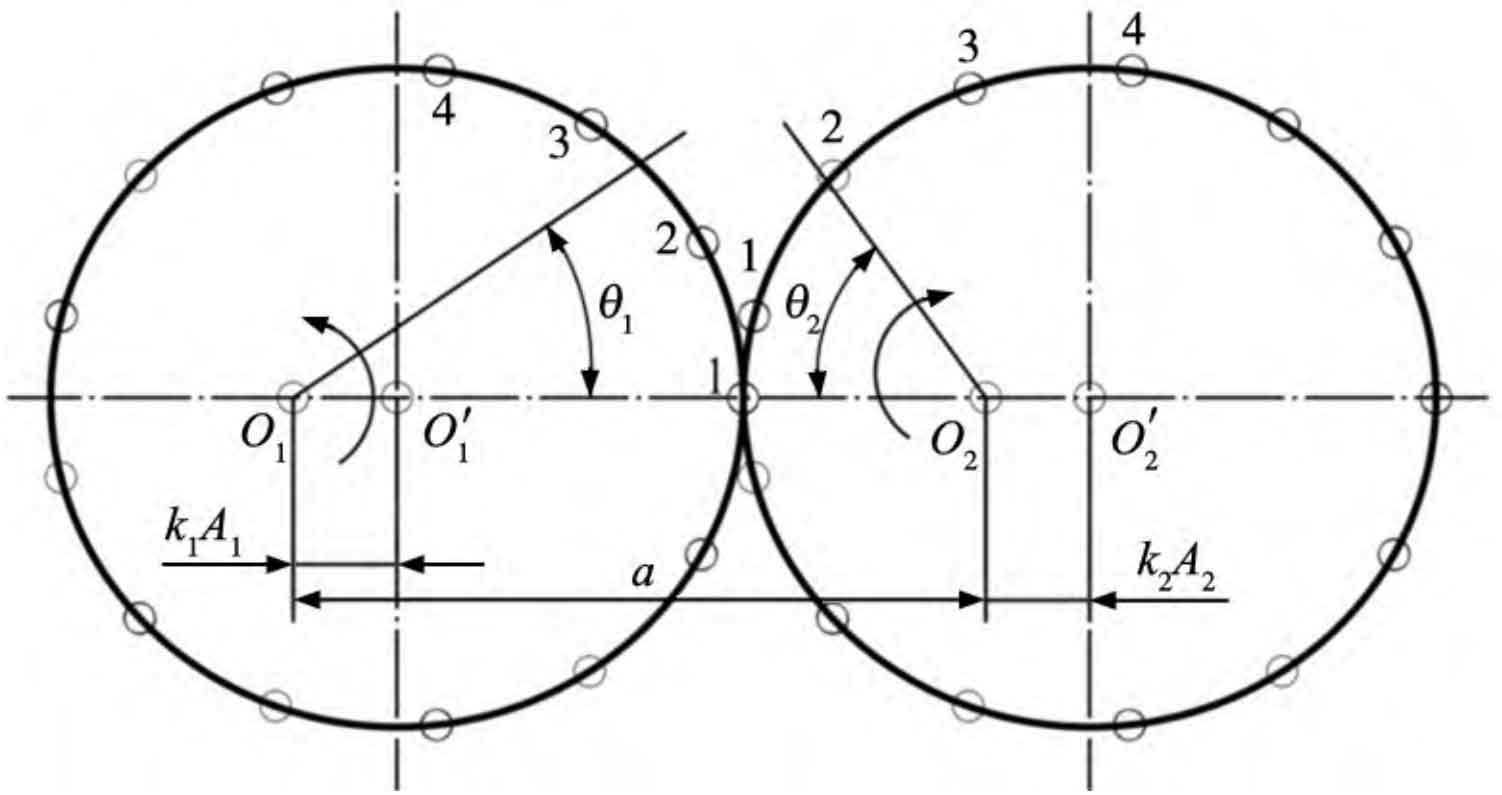
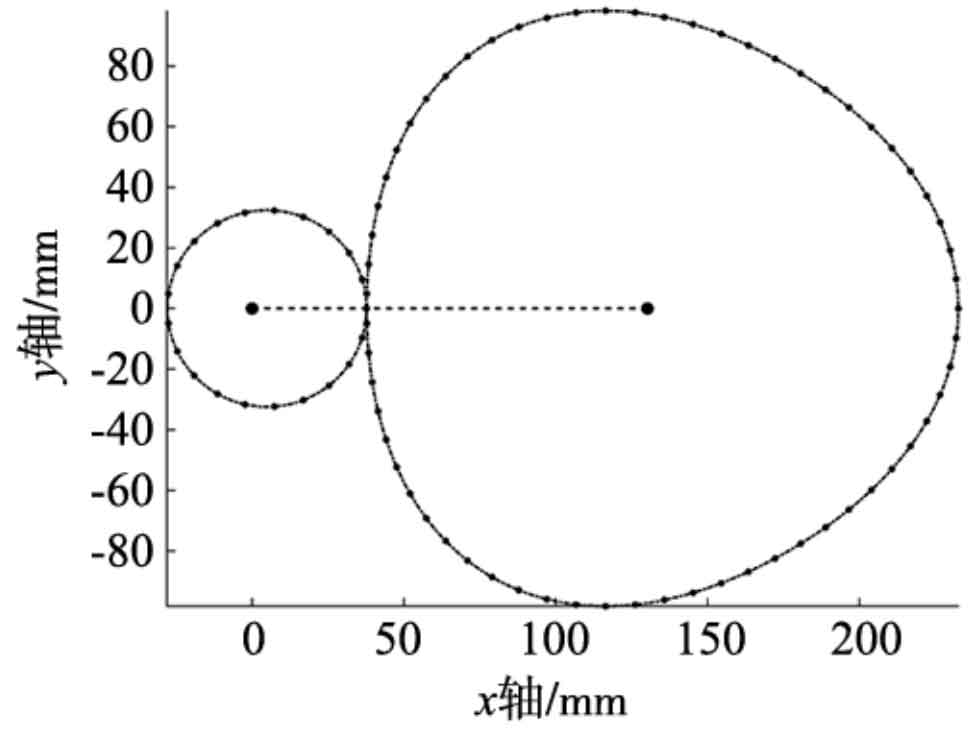
For non circular helical gears, due to the unequal curvature radii of their pitch curves, the meshing teeth must be paired one by one to ensure the normal operation of the non circular helical gears. According to the research of Wu Xutang et al., when the order ni of a non circular helical gear is 1, the number of teeth zi of the non circular helical gear is generally designed to be odd. It is stipulated that one end of the long axis of the driving wheel pitch curve should be the tooth, and the opposite end should be the tooth groove, while the driven wheel is opposite; When the order ni of a non circular helical gear is 2, the number of teeth zi of the non circular helical gear should satisfy zi=4C+2 (C is a positive integer); When ni>2, the number of teeth in non circular helical gears zi=niC1 (C1 is odd). According to Figure 1, during the meshing process, the starting meshing point should be calculated from the tangent point of the pitch curve at Figure 1. Finally, the position distribution of non circular helical gear teeth is shown in Figure 2, with the “·” point representing the tooth position.
3. Calculate the radius of curvature and the position of the curvature center
By using formulas, the curvature radius R1 × z=(r1… rj… rz) and the curvature center coordinate matrix C3 × z=(c1… cj… cz) corresponding to each non circular helical gear tooth can be calculated separately. Figure 3 shows the change in curvature radius of the driving and driven wheels during one revolution, with the “·” point in Figure 3 representing the curvature radius at the tooth position of the non circular helical gear.
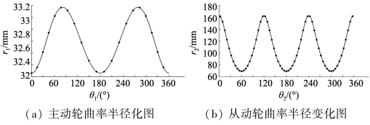
As shown in Figure 3, the curvature radii of the main and driven wheels vary periodically and symmetrically. Symmetrical operations can be performed on the tooth profile based on this change to increase the efficiency of modeling non circular helical gears.
4. Calculate other parameters
By obtaining the known parameters and the parameters in Tables 1 and 2, the corresponding base circle radius RB1 × z=(rb1… rbj… rbz), lower end involute rotation angle ROT11 × z=(rot11… rot1j… rot1z) The upper end profile is based on the rotation angle ROT21 × z=(rot21… rot2j… rot2z) of the end profile and the helix pitch S1 × z=(s1… sj… sz) on the base cylinder, except for the intersection line A
The parameters for non circular helical gears are basically completed, except for the set matrix G=(G1… Gj… Gz). The relevant calculation formulas are as follows:
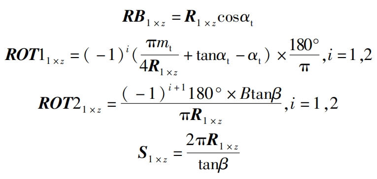
Due to the fact that during the modeling process, when drawing an involute through an equation, the starting point of the involute’s pitch angle is at the center of the non circular helical gear teeth and not at the root, its rotation angle is calculated using a formula, and its rotation direction is determined based on the pitch angle direction of the involute.
In the modeling process, when the end face profile is swept along the intersection line, it is necessary to twist the angle to avoid changes in the shape of the end face involute profile. The driving wheel (i=1) is right-handed and has a positive twist angle; The driven wheel (i=2) is left-handed and has a negative twist angle.
5. Modeling of non circular helical gears
Integrate Table 1, Table 2, and the relevant parameters involved in the above calculations in Excel, use the batch variable extraction operation of Zhongwang 3D, import the data, and complete the preparation work before modeling.
5.1 Drawing of relevant curves and drawing of coordinate points and straight lines
After importing the data into Zhongwang 3D, click on “Wireframe Curve Equation” and enter the nodal curve equation. Since the parameters related to the nodal curve have been imported, simply enter the formula and click OK.
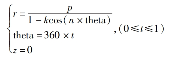
Using the offset command, draw the non circular helical gear tooth top curve and tooth root curve separately, with offsets of ha (outward) and hf (inward). Another Boolean curve with a sufficiently small offset (0.5mm) inward should be drawn as the baseline for the tooth root curve, in order to achieve the Boolean addition operation during the final tooth root curve stretching operation.
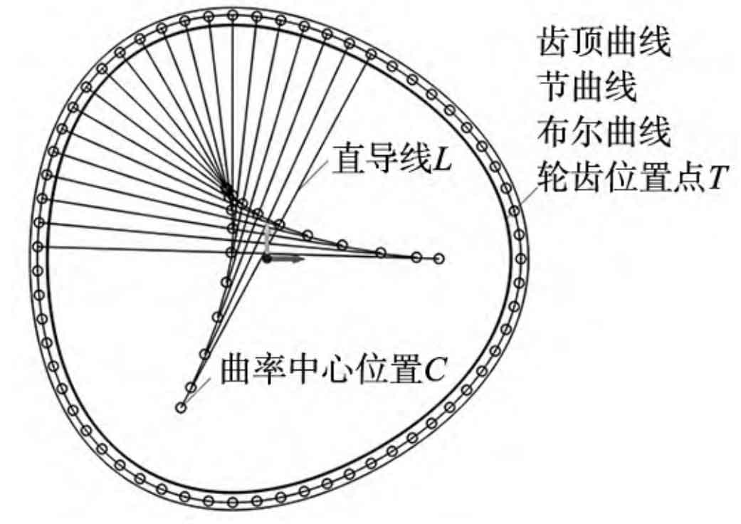
By using the point drawing command, select the curvature center coordinates C3 × z=(c1… cj… cz) and non circular helical gear tooth center coordinates T3 × z=(t1… tj… tz) of the related points and lines in the variable browser of Figure 4, respectively, to complete the drawing of the related points. Finally, draw the set of straight wires L controlled by all corresponding two points (cj, tj), as shown in Figure 4.
5.2 Drawing of Involute Spiral Surface and Obtaining Intersection and Involute Lines
According to Figure 3, the main geometric curves formed by the involute helical surface include the base cylinder helix ABC and the oblique line KM, and the drawing process steps are as follows:
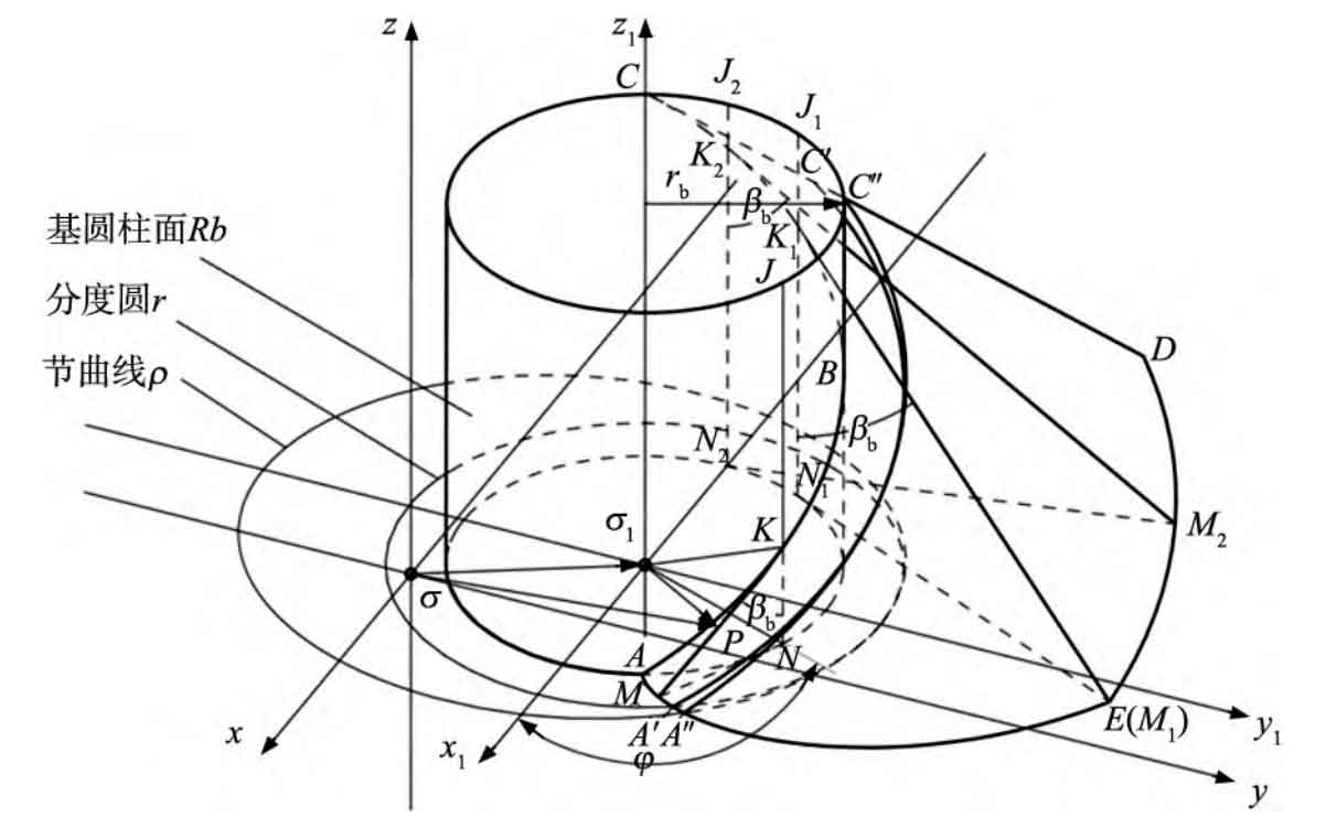
Step 1: Draw the set of cylindrical helical lines HLrb on the tooth base of non circular helical gears. When drawing the base cylinder helix, select the corresponding axis position (curvature center position C), corresponding starting point (tooth position T), corresponding base circle radius (RB), helix height (S/2), and pitch (S) of the gear teeth to complete the drawing of the base cylinder helix.
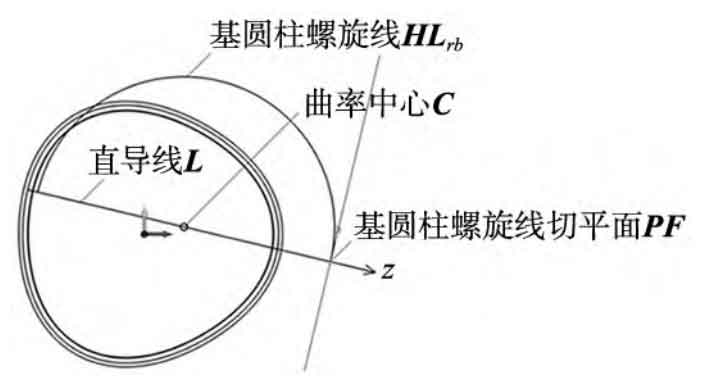
Step 2: Draw the sketch plane set PF where the diagonal line KM set OL is located. Using the distant endpoint of the base cylinder helix as the positioning point, the tangent plane of the base cylinder helix and the tangent plane at the tooth of a single non circular helical gear in Figure 7 should be drawn in the direction indicated by the set of straight wires L as the plane z-axis (plane normal direction), and the tangent plane collection PF of the base cylinder helix at the positioning point should be established. The tangent plane of a single tooth is drawn as shown in Figure 7.
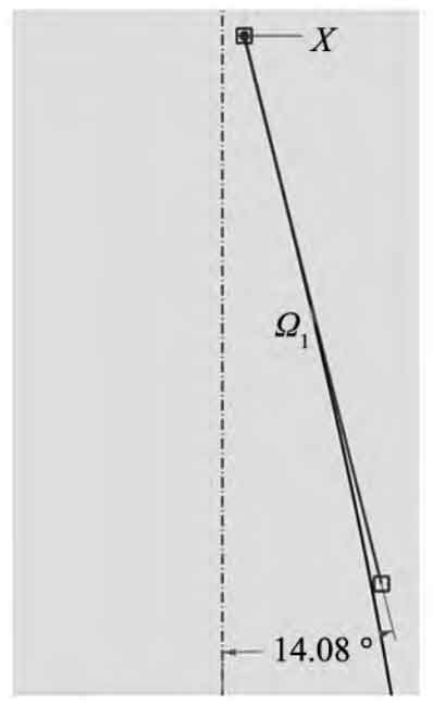
Step 3: Draw the diagonal line KM set OL. Draw the tangent plane set PF drawn in step 3 as the sketch plane, and then draw the oblique line KM starting from the far end of the base cylinder helix, making it tangent to the base cylinder helix. The length of the oblique line is appropriate, and the final drawing effect is shown in Figure 8, with an angle of the base cylinder helix angle β The value of b verified the correctness of the drawing method.
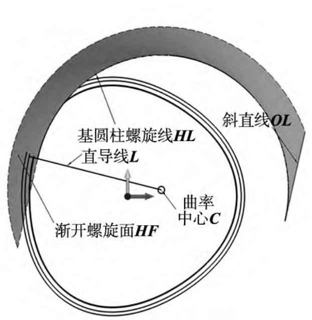
Step 4: Draw the set of involute spiral surfaces HF. Using the oblique line KM set OL as the contour and the corresponding base cylinder helix set HLrb as the path, sweep to obtain the involute helix set HF. The drawing effect of a single involute helix is shown in Figure 9.
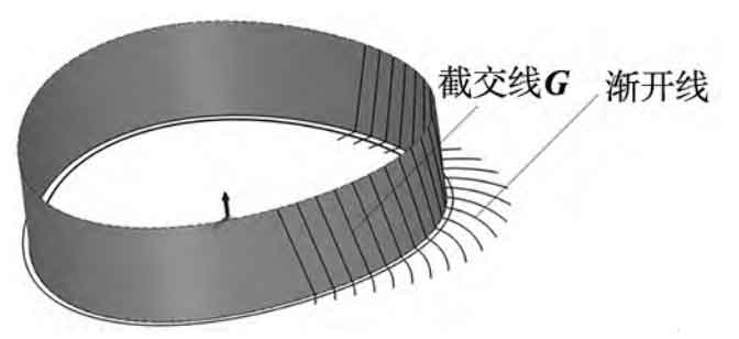
Step 5: Cut the set of involute helical surfaces HF to the tooth width B, stretch the pitch curve as a curved surface, and obtain the intersection curve G of the intersection line and involute of the phase diagram 10 of the pitch curve cylinder and the set of involute helical surfaces HF. The intersection curve between the bottom plane and the set of involute helices HF is the involute on one side of the end face, as shown in Figure 10.
5.3 Drawing of End Face Tooth Profile and Diagonal Teeth
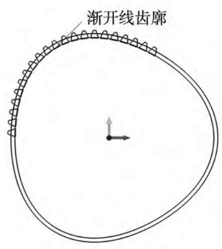
Establish a local coordinate system for the curvature center coordinate C, with the x-axis pointing towards its corresponding straight wire L direction. Establish the normal plane SF of the pitch curve at the tooth of a non circular helical gear. On this coordinate system, rotate the generated left involute by ROT1 angle and mirror it symmetrically, with the mirror surface SF, to generate a complete involute drawing. Finally, trim it and complete the drawing of the involute tooth profile INV, as shown in Figure 11.
Using the involute non circular helical gear tooth profile INV as the sweep profile, the intersection line G as the sweep path, and ROT2 as the twist angle, generate a swept solid, and finally perform a polygonal array to generate a complete helical gear.
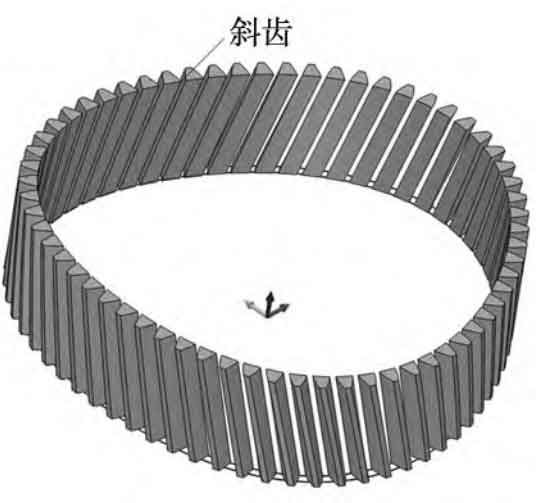
5.4 Closing work for non circular helical gears
Stretch with a pitch curve, with a stretching length of tooth width B, and perform Boolean Figure 13 on the main and driven wheel models to make them integrated with the helical teeth. Finally, fillet the tooth root and perform a polygonal array, draw the shaft hole, and complete the modeling of high-order non circular helical gears. The same method is used for modeling the driving wheel.
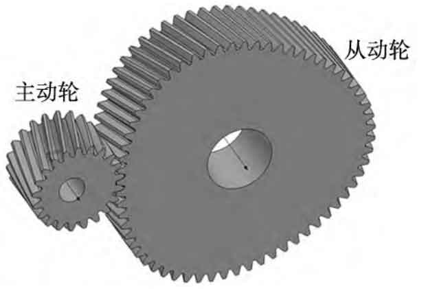
6. Kinematic simulation analysis
After the modeling is completed, it is necessary to conduct kinematic simulation analysis on the non circular helical gear to check whether the non circular gear pair interferes and meets the required variable transmission ratio. Import the model established by Zhongwang 3D into Creo, and add rotating pairs and related constraints as required to complete the assembly of the main and driven wheels. Due to the non circular helical gear transmission ratio being in a functional form, it is not possible to use a general gear pair for connection. Therefore, it is proposed to add different servo motors as driving sources to the main and driven wheels respectively, so that the main and driven wheels can rotate according to their respective motor parameters, and check the interference situation during this process. Set the driving wheel to a speed of ω 1=60 °/s, that is, the driving wheel rotates uniformly at this speed; The rotational speed of the driven wheel should be calculated according to equation, that is, based on the transmission ratio function i12 and ω 1. The driven wheel rotates in a functional form.

After the driver source is set up, it runs and uses Creo’s global collision detection function to analyze the running data. When a red area appears in the meshing area of the non circular helical gear pair, interference occurs. When conducting motion simulation analysis on non circular helical gears, it was found that their overall operating performance is good, but some teeth have color areas, indicating that there is slight interference in the model, which needs to be solved.
For non circular helical gears, the main methods to solve interference include correcting tooth profile and adjusting center distance. This example solves the interference problem by adjusting the center distance appropriately. Compared to the standard center distance a=130.197mm, the adjusted center distance a ′=130.658mm can completely avoid interference problems, with a center distance increment of no more than 0.36%, meeting most application scenarios.
7. Conclusion
(1) Due to the excessive number of parameters involved in drawing non circular helical gears, it is necessary to utilize the powerful calculation functions of MATLAB to process their related parameters, and then use the Excel parameters of Zhongwang 3D to import them in bulk, greatly saving the drawing time of non circular helical gears;
(2) This article uses the intersection curve (intersection line) of the involute helical surface and the pitch curve cylindrical surface to replace the traditional gear tooth helix, effectively solving the problem of uneven deviation of the traditional helix, reducing the interference rate of the gear teeth to a certain extent and enhancing their overlap. The rationality of the intersection line was demonstrated through deduction, and its feasibility was demonstrated through modeling;
(3) When CAD modeling non circular helical gears, a detailed description of the modeling process of high-order non circular helical gears based on the converted tooth profile method is provided, which has important reference significance for the modeling of most non circular helical gears and non circular spur gears;
(4) Using Creo’s global collision detection device to check the interference situation of non circular helical gears, the interference problem is solved by adjusting the center distance, and the adjustment increment does not exceed 0.36%. This proves that the model meets most application scenarios and is of great significance for later research on the meshing stiffness of non circular helical gears.
