1.Normal profile of profile rack
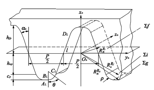
The variable tooth thickness helical gear is generated by the envelope of the generating rack. Figure 2 shows a part of the generating rack and its normal profile. Sn (on xn yn Zn) is the coordinate system connected with the normal plane of the generating rack. Yn and Zn are located on the dividing plane of the generating rack, xn is located on the symmetrical plane of the normal profile, and is perpendicular to the dividing plane of the generating rack.

The equations for each segment of the tooth profile are as follows
a. The straight-line segment (ckdk) envelops the involute tooth profile between the tooth root and the tooth top of the variable tooth thickness helical gear. The equation in the coordinate system SN is:
Rnki (l) =[lcosαn-hanmn± (lsinαn-hanmntanαn+πmn4) 01]
Where, rnki is the position vector of any point on the straight line in SN; α n is the normal pressure angle; Mn is the normal modulus; h * an is the coefficient of addendum; L is the variable, k = L, R, l is the left profile of the profile rack; R is the right profile of the profile rack, ± definition: the above symbol is used for the right profile of the profile rack, and the following symbol is used for the left profile of the profile rack.
b. The fillet part of tooth top (bkck) envelops the transition curve of variable tooth thickness helical gear, and the equation in the coordinate system SN is as follows:
Rnkf (θ) =[-hanmn-ρcosθ-ρsinαn± (πmn4+hanmntanαn+ρcosαn-ρsinαn) 01]
Where, rnkf is the position vector of any point on the arc segment in Sn, and θ is the variable.
c. The straight section of tooth top (akbk) envelops the tooth root of variable tooth thickness helical gear, and the equation in the coordinate system SN is as follows:
Rnkg (e) =[- (hanmn+cn) mn± (πmn4+hanmntanαn+ρcosαn) +e (πmn4+hanmntanαn+ρcosαn) ]01]
Where, rnkg is the position vector of any point on the straight line segment in Sn, c * n is the top clearance coefficient, and E is the variable.
2.Establishment and transformation of gear cutting coordinate system
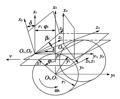
When machining the variable tooth thickness helical gear with the profile rack, the tooth cutting coordinate system is established as shown in Fig. 3. Sn (on xnynzn) is the normal plane coordinate system, SP (OP xpypzp) is the end plane coordinate system, and SC (OC xcyczc) is the nodal plane coordinate system. The coordinate system Sn moves in a straight line along the straight line opon together with the normal section line of the generating rack. The straight line opon is located in the dividing plane of the shaping rack and forms the angle β C with the ZP axis. The position of the origin of Sn coordinate is determined by the variable parameter u = |ΟΟΟ¯ӟ.

The transformation relationship between normal plane coordinate and end face coordinate is
Rpki (f) (g) =MpnRnki (f) (g)
among
Μpn=[10000cosβcsinβcusinβc0-sinβccosβcucosβc0001]
The conversion relationship between the end face coordinate and the nodal plane coordinate is
Rcki (f) (g) =McpRpki (f) (g)
among
Μcp=[cosδ0sinδ00100-sinδ0cosδ00001]
The equations of ∑ I, ∑ F and ∑ g of the profile rack surface in the coordinate system SC can be obtained by combining equations (4) and (5)
{Rcki (u, l) =[Rnxkicosδ-Rnykisinβcsinδ+ucosβcsinδRnykicosβc+usinβc-Rnxkisinδ-Rnykisinβccosδ+ucosβccosδ1]Rckf (u, θ) =[Rnxkfcosδ-Rnykfsinβcsinδ+ucosβcsinδRnykfcosβc+usinβc-Rnxkfsinδ-Rnykfsinβccosδ+ucosβccosδ1]Rckg (u, e) =[Rnxkgcosδ-Rnykgsinβcsinδ+ucosβcsinδRnykgcosβc+usinβc-Rnxkgsinδ-Rnykgsinβccosδ+ucosβccosδ1]
Where rcki, rckf and rckg are the position vectors of any point on the generating rack surface Σ I, Σ F and Σ g in the coordinate system.
