
The worm-helical gear transmission pair, as a type of crossed-axis point contact transmission, has significant applications in various fields such as automobiles, smart appliances, and robotics. Mastering its time-varying mesh stiffness and the nonlinear dynamic behaviors caused by factors such as mesh backlash and errors is crucial for vibration and noise reduction. This paper modifies and solves the theoretical time-varying mesh stiffness of the worm-helical gear transmission pair based on the potential energy method. A dynamic model considering backlash, comprehensive errors, and time-varying mesh stiffness is established. The system dynamics equations are numerically solved using the 4th-5th order Runge-Kutta method. Dynamic characteristic curves of the worm-helical gear transmission pair are obtained. Combining time-domain plots, Poincaré plots, and FFT spectra, the influences of factors such as backlash, damping ratio, and load on the vibration and impact states of the transmission pair are analyzed. The results show that smaller error amplitudes and larger damping ratios can stabilize the system in periodic motion. These findings provide guidance for optimizing the vibration and noise of worm-helical gear transmission systems.
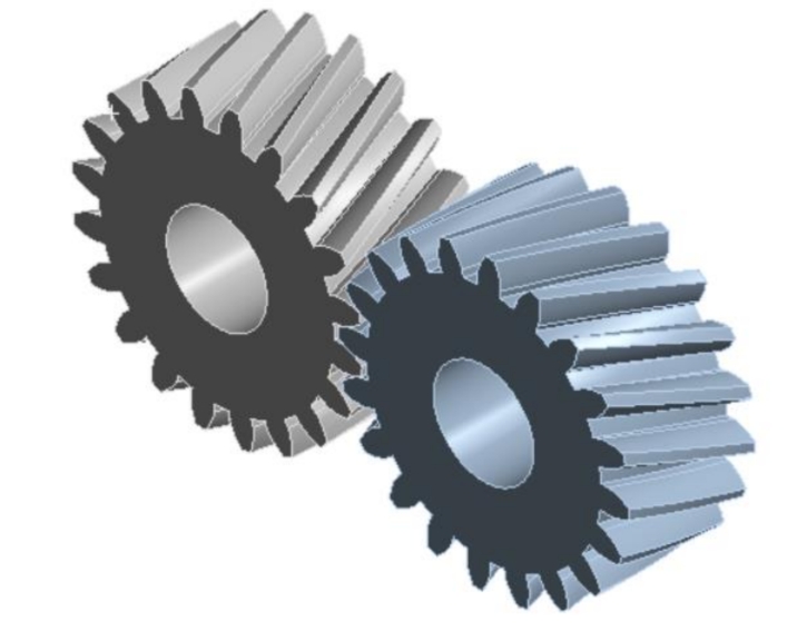
The worm-helical gear transmission pair consists of a worm gear and a helical gear, forming a spatial crossed gear pair with point contact between the meshing surfaces. It offers advantages such as large transmission ratio, compact structure, good workmanship, low vibration and noise, and low cost. It is widely used in mechanical transmission fields such as automobiles, smart appliances, robotics, and space mechanisms, effectively extending the service life of mechanical transmissions.
Previous studies on worm-helical gear transmissions have mainly focused on statics, including the analysis of gear tooth contact areas, stress changes, and wear testing of different materials. However, the internal excitations such as gear stiffness and error excitations are significant causes of vibration and noise in gear transmission systems. The time-varying mesh stiffness of gears, as an important internal excitation, is the basis for studying gear dynamic characteristics. Its calculation has been a crucial topic in gear research both domestically and internationally. Additionally, factors such as backlash, error amplitudes, and loads are external causes of vibration and noise in worm-helical gear transmission pairs.
This paper modifies and solves the theoretical time-varying mesh stiffness of the worm-helical gear transmission pair based on the potential energy method and verifies it using the finite element method. A dynamic model considering backlash, transmission errors, and time-varying mesh stiffness is established, and the 4th-5th order Runge-Kutta method is used for numerical solution. By combining time-domain plots, Poincaré plots, and FFT spectra, the influences of internal and external factors such as backlash, damping, and load on the vibration and impact states of the transmission pair are effectively analyzed.
Gear mesh stiffness refers to the overall stiffness of all pairs of teeth involved in meshing within a complete meshing cycle. It is mainly related to the elastic deformation of individual meshing teeth, the sum of the elastic deformations of pairs of meshing teeth, and the contact ratio of the meshing gear pair. The basic formula for calculating gear mesh stiffness is the ratio of the applied force F to the displacement x. In gears, the applied force is the meshing force generated during meshing, and the deformation of the gear is a combination of contact deformation, bending deformation, shear deformation, and axial compression deformation caused by the contact force. Therefore, the mesh stiffness of the gear can be composed of the Hertz stiffness kh, bending stiffness kb, shear stiffness ks, compression stiffness ka, and base stiffness kf corresponding to the above deformations.
Currently, the common potential energy method simplifies the gear teeth as a cantilever beam on the base circle. However, the starting point of the gear teeth is the root circle, which does not coincide with the base circle, leading to errors in the mesh stiffness of the gear pair. Moreover, the conjugate tooth surfaces of the worm-helical gear transmission pair are theoretically point contacts, unlike the line contacts of ordinary cylindrical gears. The meshing-in and meshing-out points are not on the gear end face. When the gear pair tooth surfaces are loaded, they deform, forming an instantaneous elliptical contact area in the tangent plane at the meshing point. The tooth surface contact trace is an inclined curve. For calculation convenience, discrete meshing points can be simplified into a meshing line. Therefore, when calculating the time-varying mesh stiffness of the worm-helical gear transmission pair, it is necessary to convert the length of the time-varying contact line within the meshing cycle of an ordinary cylindrical gear pair into the length of the long semi-axis of the contact ellipse at different meshing points and calculate the effective tooth width of the gear pair. The Hertz stiffness, bending stiffness, shear stiffness, and compression stiffness can be calculated and solved using the following formulas.