
In my research on plastic-steel worm gear transmissions, I focus on the thermal behavior under steady-state conditions. The combination of a steel worm and a plastic worm wheel (made of POM) offers advantages such as low cost, light weight, low noise, flexible design, large single-stage ratio, and excellent insulation. These gears are widely used in automotive and household applications. For mass production, the spiral worm wheel can be manufactured by injection molding, further reducing cost compared to hobbing. However, the mechanical properties of engineering plastics—elastic modulus, sliding friction coefficient—are highly temperature-dependent. Therefore, a thorough thermal analysis is essential to determine the load capacity of such gear pairs. The operating temperature must remain below the material’s limit to prevent thermal failure. To minimize cost, I aim to reduce the gear meshing temperature through effective heat dissipation, allowing smaller gears to achieve higher load capacity.
Previous studies have measured temperature in spiral worm gears using contact probes, but a macroscopic theoretical analysis of the heat transfer process is lacking. The thermal network method, based on the thermal–electrical analogy, is well-suited for analyzing complex heat dissipation mechanisms and nodal temperatures. Some researchers applied the thermal network method to planetary gears, while others built a thermal network model for a six-speed automotive gearbox. Most existing work focuses on spur gears and solves systems of equations for nodal temperatures. In contrast, my study addresses spiral worm gears, which have distinct heat dissipation laws, loading conditions, and power losses compared to spur gears. Moreover, the gear is cooled by natural air convection, differing from oil or forced air cooling. Using Simscape to build the thermal network model offers advantages: it is intuitive, easy to adjust when the gear layout changes, and allows simultaneous measurement of all nodal temperatures. For these reasons, I use Simscape software to perform a steady-state thermal analysis of a plastic–steel spiral worm gear.
Principle of Thermal Network Analysis
Simscape, built on Simulink, includes a thermal library for modeling heat transfer networks. The principle of thermal analysis for a worm gear system is illustrated conceptually as follows: a power loss source is modeled as an ideal heat flow source; heat flows through conductive and convective thermal resistances, generating temperature differences; the ambient temperature is set by an ideal temperature source; the entire system is connected to a solver for simulation; temperature and heat flow sensors directly measure nodal temperatures and branch heat flows.
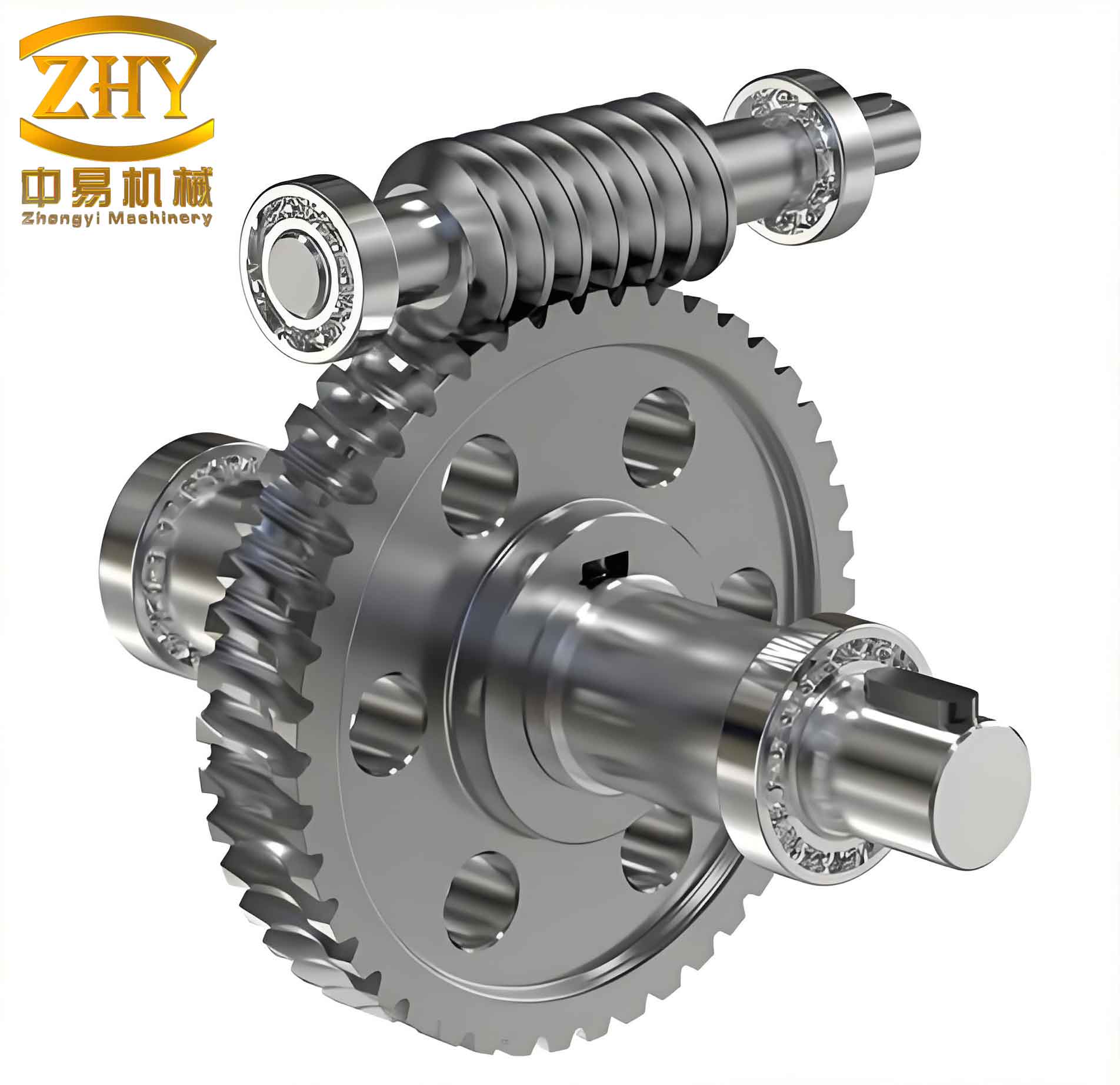
I consider the spiral worm gear from a test bench. The worm is made of 45 steel, the worm wheel of POM (polyoxymethylene). Bearings are single-row deep-groove ball bearings with double seals. The gear ratio is 40:1, the output wheel helix angle is 7.5°, input speed 1500 rpm, center distance 30 mm, and cooling by natural air. The thermal network nodes are defined as follows:
| Node | Description |
|---|---|
| 0 | Ambient air |
| 1 | Worm tooth surface (meshing zone) |
| 2 | Worm wheel tooth surface (meshing zone) |
| 3 | Midpoint of worm non-meshing region near bearing A |
| 4 | Midpoint of worm non-meshing region near bearing B |
| 5 | Midpoint of worm wheel body |
| 6 | Contact surface between worm wheel and worm shaft |
| 7 | Inner ring of bearing A |
| 8 | Inner ring of bearing B |
| 9 | Inner ring of bearing C |
| 10 | Inner ring of bearing D |
| 11 | Gearbox housing and outer rings of all bearings (treated as isothermal) |
Because the system operates at low temperatures, radiation is neglected. During meshing, multiple tooth pairs are in contact simultaneously, and the temperature in the meshing zone is assumed constant — serving as the starting temperature for convection to the gearbox air. For the non-meshing regions, conductive thermal resistance causes a temperature drop, so the midpoint temperature is taken as the initial temperature for convection. The gearbox is made of aluminum (high thermal conductivity) and can be considered isothermal. Bearings’ inner rings are in tight contact with shafts, outer rings with the gearbox; therefore, I treat the gearbox, bearing outer rings, and their contact surfaces as a single node. The gear base is connected to a large chassis, so the base bottom temperature equals ambient temperature and is directly measured.
The thermal network diagram includes two heat sources: the power loss at the worm–worm wheel mesh (steel–plastic) and the power losses in bearings A, B, C, D. For each bearing, the heat generation is split equally between the inner and outer races. The network comprises thermal resistances between each pair of connected nodes. I constructed the thermal network model in Simscape, using heat flow sensors and temperature sensors to measure all branch heat flows and nodal temperatures.
Power Loss and Thermal Resistance Models
Power loss at the worm–wheel mesh is primarily due to sliding friction. Empirical formulas for plastic–steel spiral worm gears have been established in the literature. The total frictional power loss $P_{mesh}$ (sum of losses in both the worm and wheel) is given by:
$$P_{mesh} = \frac{2\pi \, T_2 \, n_1}{30} \, \eta_{loss}$$
where $\eta_{loss}$ is the loss factor derived from the gear geometry and friction coefficient. The friction coefficient $\mu$ depends on sliding velocity $v_s$, center distance $a$, and other parameters:
$$\mu = \frac{a_0 \sin\alpha + a_1 \sin^2\alpha}{2} + a_3 \frac{v_s^2}{a_4} + a_5 \frac{v_s^2}{a_6} + a_7 \frac{v_s^2}{a_8} + a_9$$
For POM worm wheels, the coefficients are determined experimentally. I list the coefficients in the table below.
| Coefficient | Value |
|---|---|
| $a_0$ | 10.864 |
| $a_1$ | 2.809×10⁻³ |
| $a_2$ | 0.97017 |
| $a_3$ | 3.1811×10⁻⁴ |
| $a_4$ | 0.74456 |
| $a_5$ | 1.5181 |
| $a_6$ | 6.6791×10⁻⁴ |
| $a_7$ | 0.036533 |
| $a_8$ | 2.5208 |
| $a_9$ | 0.26169 |
Bearing power losses are computed using the Palmgren method. For each bearing, the frictional moment $M$ is:
$$M = f_0 (P_0) \, d_m + f_1 \, F_1 \, d_m$$
where $d_m$ is the mean bearing diameter, $F_1$ the equivalent load, $f_0$ and $f_1$ are lubrication- and load-dependent coefficients. The power loss for a bearing is $P_{bearing} = M \cdot \omega$ with $\omega$ the shaft angular speed.
For natural air convection, I treated the gear surfaces as flat plates under forced convection. The Nusselt number for laminar flow (Reynolds < 10⁵) is:
$$Nu = 0.644 \, Re^{1/2} \, Pr^{1/3}$$
Conductive and convective thermal resistances are calculated using standard heat transfer formulas. For a cylindrical solid of length $L$, cross-sectional area $A$, and thermal conductivity $k$, the conductive resistance is $R_{cond} = L/(kA)$. For convection from a surface area $A_s$ with heat transfer coefficient $h$, $R_{conv} = 1/(h A_s)$.
I assembled the complete thermal resistance network in Simscape, including all nodes and heat sources. The simulation yields steady-state temperatures at each node and heat flows through each branch.
Simulation Results and Analysis
I ran simulations for various output torque levels (from 0.5 Nm to 3.0 Nm) while keeping the input speed constant at 1500 rpm. The temperatures of key nodes (worm meshing point, worm wheel meshing point, inner rings of bearings A, B, C, D, and gearbox) were recorded. The results show that all nodal temperatures increase linearly with torque. The worm temperature is most sensitive to torque. Therefore, when evaluating load capacity, material parameters should be selected based on the expected torque. In gear design, reducing the required torque through efficient tooth profiles or using smaller gears can save volume and cost.
The worm temperature is significantly higher than all other node temperatures. This occurs because steel has much higher thermal conductivity than plastic; consequently, the majority of the frictional heat generated at the mesh is conducted away through the worm. The temperature difference between the worm and the worm wheel is large. To prevent thermal failure of the plastic wheel (e.g., melting at the tooth surface), the limiting temperature should be based on the worm temperature (the hotter component). Hence, improving heat dissipation from the worm is the top priority. Under limited development resources, I should focus on enhancing the worm’s cooling rather than the plastic wheel’s. The worm temperature is much higher than the bearing inner ring temperatures, indicating that internal conduction along the worm shaft plays a major role in heat removal.
Branch heat flow analysis reveals that approximately 92% of the frictional heat generated at the worm–wheel mesh is transferred via conduction through the worm and then through the bearings to the gearbox. Only about 8% is dissipated by convection to the gearbox air. Therefore, the most effective way to reduce the worm’s temperature is to reduce the conductive thermal resistance along the worm–bearing path. Two practical approaches are: (1) using a worm material with higher thermal conductivity; (2) shortening the worm length to reduce the conduction path.
I performed additional simulations to quantify these effects. First, I replaced the original 45 steel (thermal conductivity ≈ 45 W/(m·K)) with an alternative steel having a conductivity 5 W/(m·K) higher (50 W/(m·K)). Second, I reduced the worm length by 2 mm. The results are summarized in the table below for a torque of 2.5 Nm.
| Configuration | Worm temperature (K above ambient) | Reduction (K) |
|---|---|---|
| Original (45 steel, original length) | 78.5 | — |
| Higher conductivity (50 W/(m·K)) | 68.3 | 10.2 |
| Shortened worm (−2 mm) | 73.1 | 5.4 |
The results confirm that increasing thermal conductivity by 5 W/(m·K) reduces the worm temperature by about 10 K under high load, while shortening the worm by 2 mm yields about 5 K reduction. Both approaches effectively lower the meshing temperature, enabling the use of smaller gears for the same load capacity, thus reducing cost.
Conclusion
I developed a steady-state thermal network model for a plastic–steel spiral worm gear using Simscape. The model comprehensively analyzes temperature and heat flow distribution. The simulation reveals that the worm temperature dominates the thermal field, and the primary heat dissipation path is conduction through the worm and bearings to the gearbox. In design, improving the worm’s conductive heat transfer is the most effective strategy. Using a worm material with higher thermal conductivity or reducing the worm length can significantly lower the worm temperature, allowing the gear pair to achieve higher load capacity with a smaller envelope and lower cost. The thermal network method implemented in Simscape provides a flexible and intuitive tool for thermal analysis of complex gear systems.