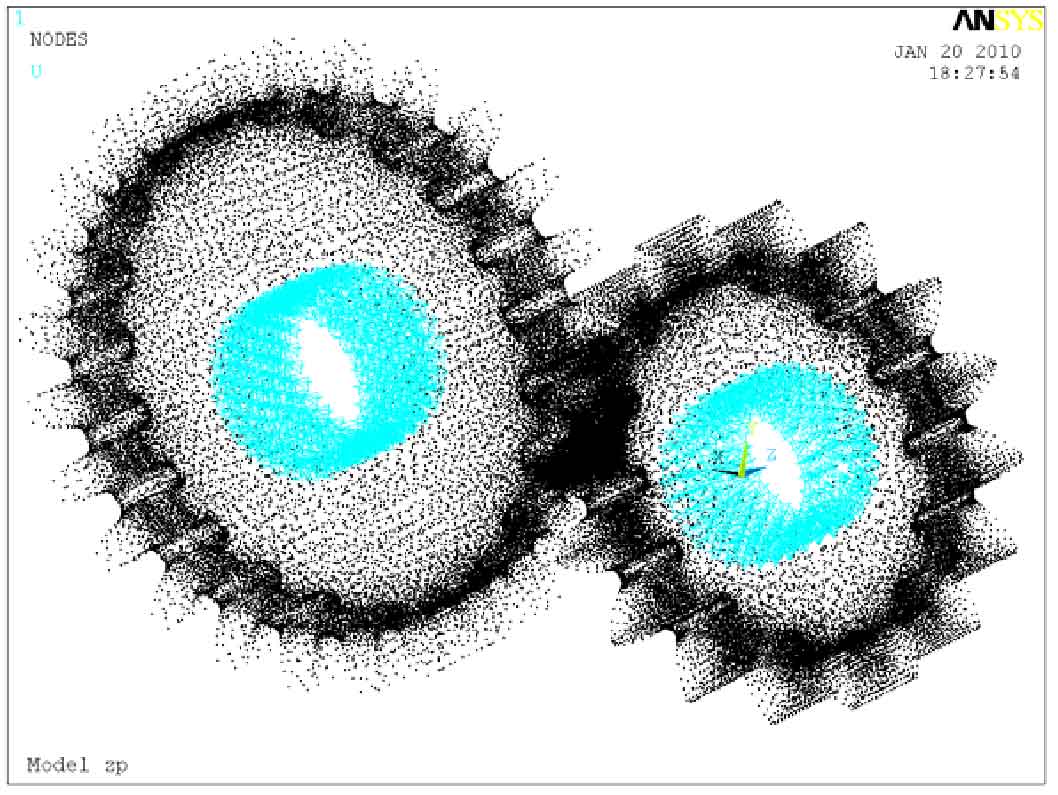
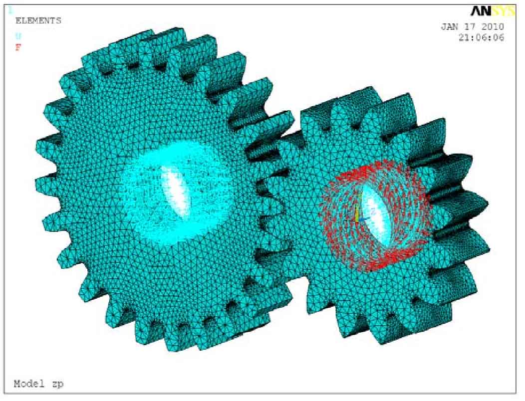
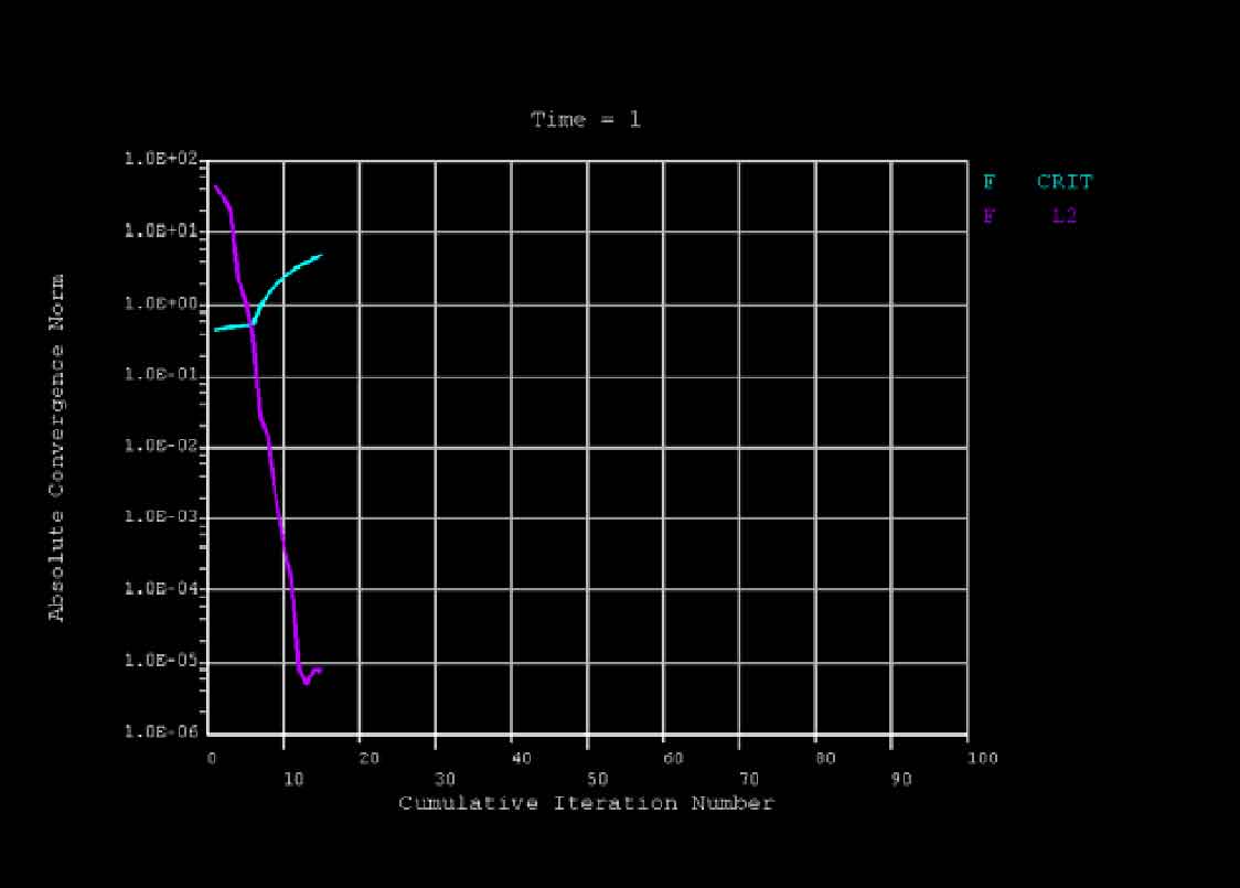
Keep the contact boundary condition with smooth gear consistent with the loading setting treatment method, restrict the degrees of freedom of all nodes in the inner hole of large gear, and select the constant value of all DOF as 0; Constrain the degrees of freedom of all nodes in the x-axis and z-axis directions of the pinion inner hole. Select the constant value of UX and UZ as 0. Figure 1 shows the gear contact boundary conditions after constraints are applied; Select all nodes in the inner hole of the pinion and apply a certain load torque in the y-axis direction in the coordinate system by using the rotation setting. The magnitude of the load is calculated by the formula. Set the torque T2 = – 27.51 n · m in the uy direction. The schematic diagram of pinion loading after torque application is shown in Figure 2; The three-dimensional contact nonlinear solution curve of pit gear obtained by calculation is shown in Fig. 3.
CHINA LEADING ENGINEER TEAM: During 40+ Years' effort, full circle of production line were enhanced


