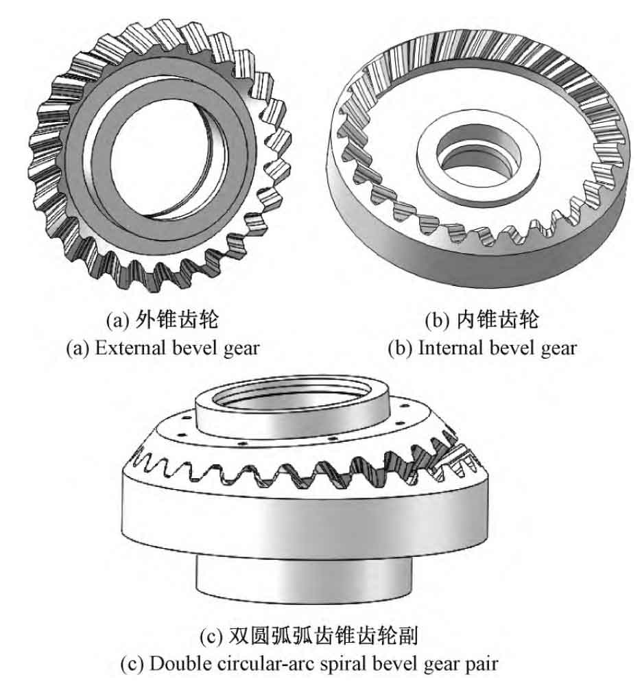
In order to obtain the 3D model of double-arc spiral bevel gear, select the geometric parameters of double-arc spiral bevel gear as shown in the table.
| Parameter name | External bevel gear | Internal bevel gear |
| Teeth number | 26 | 28 |
| Small end modules/mm | 2 | 2 |
| Nutation angle /( °) | 5 | 5 |
| Spiral angle /( °) | 5 | 5 |
| Pitch cone angle /( °) | 47.19 | 127.81 |
| Cone distance /mm | 60 | 60 |
| Tooth width /mm | 8 | 8 |
| Addendum/mm | 1.8 | 1.8 |
| Dedendum/mm | 2.15 | 2.15 |
According to the tooth surface equation of the double-arc spiral bevel gear and the geometric parameters in the table, the data point coordinates of the tooth surface can be obtained. The obtained tooth surface data is imported into SolidWorks to generate the tooth surface, and combined with the established double-arc spiral bevel gear blank, the three-dimensional model of double-arc spiral bevel gear is generated by using the surface cutting feature and the circular array feature, as shown in Figure a and Figure b. Assemble the generated inner and outer double-arc spiral bevel gears to obtain the nutation drive double-arc spiral bevel gear pair model as shown in Fig. c.

