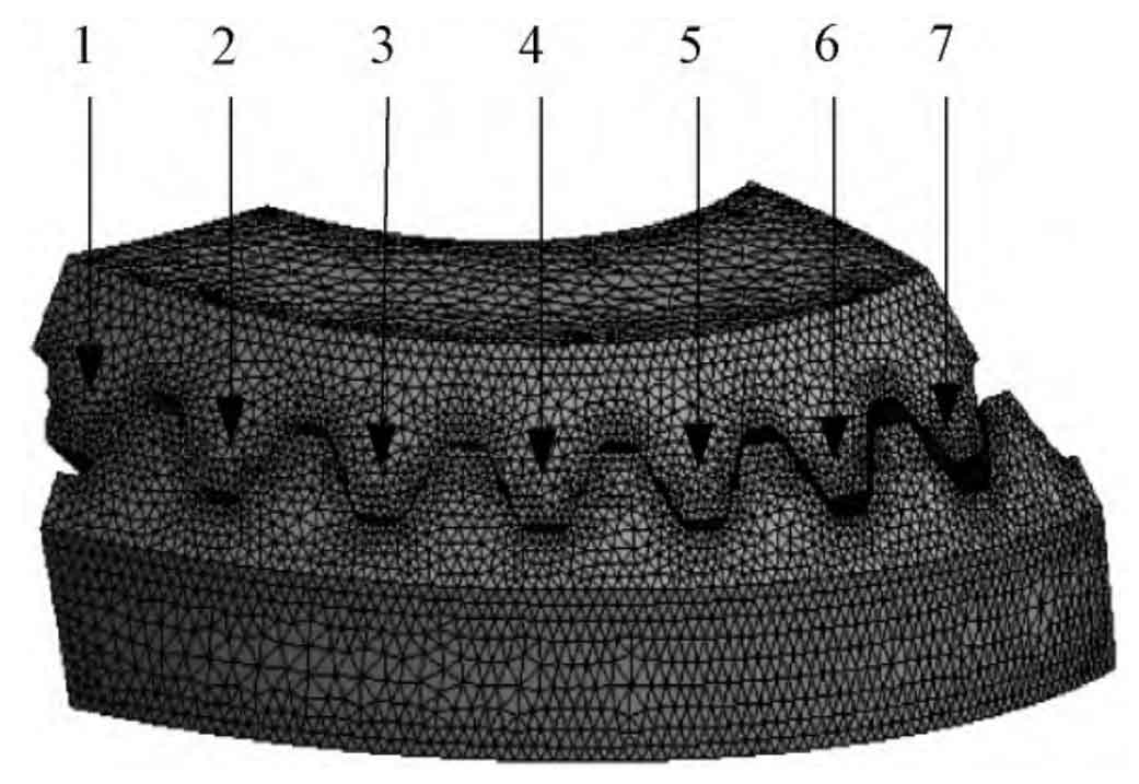
In order to improve the calculation efficiency and avoid the impact of too few contact tooth pairs on the calculation results, this paper establishes a three-dimensional model of seven-tooth pairs and imports it into the Ansys Workbench, and makes the following settings:

(1) Material definition: set the material density of the outer bevel gear and the inner bevel gear as 7 850 kg/m3, and the elastic modulus as 2 one × 105 MPa, Poisson’s ratio is 0 3。
(2) Selection of analysis module: in order to obtain the quasi-static contact characteristics of gears, the structural statics module is selected for quasi-static contact analysis of gears.
(3) Selection of contact surface: select the tooth surface of two gears as the contact surface, and set the friction coefficient of the contact surface to 0 1。
(4) Application of boundary conditions: constrain all degrees of freedom of the external bevel gear, release only the degrees of freedom of rotation around its own axis for the internal bevel gear, and constrain all other degrees of freedom.
(5) Load application: apply 120 N · m load torque to the internal bevel gear. To ensure the convergence of calculation, the load is linearly increased from 0 to the maximum value.
(6) Mesh type selection: tetrahedral elements are selected for mesh generation using free mesh generation technology. The seven-tooth finite element model is as shown in the figure, which contains 187370 elements and 278426 nodes.
