Abstract
This article presents a general parametric design method for three-dimensional (3D) modeling of involute helical gears using SolidWorks software. The method involves setting up 19 global variables and utilizing equation-driven curves to create both the sweep path and profile. Subsequently, the 3D model is refined through sweep cuts and circular patterns, resulting in an accurate helical gear model that captures both the precise involute surface and the root transition surface. This approach offers simplicity, speed, precision, and ease of modification, laying a solid foundation for rapid mechanical product design.

1. Introduction
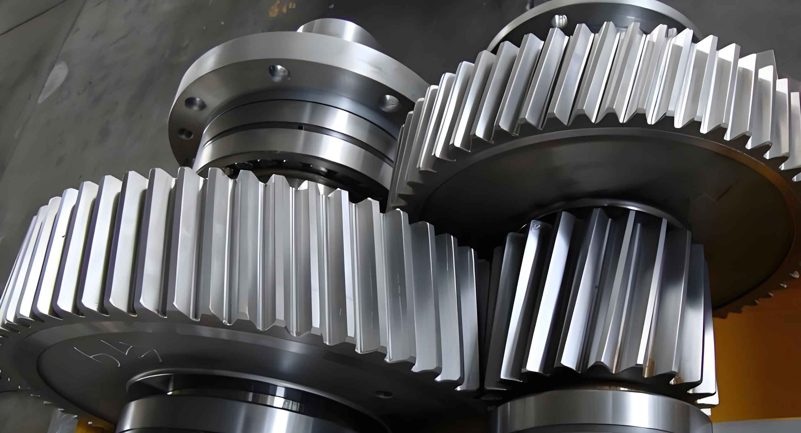
Helical gears possess numerous advantages, including smooth transmission, low noise, high load capacity, and suitability for high-speed applications. Their widespread adoption necessitates efficient and precise 3D modeling techniques for product design and analysis. SolidWorks, a computer-aided design (CAD) software, provides a powerful platform for creating accurate helical gear models. However, existing modeling methods often rely on complex external tools or programming languages, compromising simplicity and accessibility. This article introduces a straightforward method that leverages SolidWorks’ built-in features for involute helical gear modeling.
2. Modeling Approach
The proposed modeling approach involves six primary steps: inputting global variables, creating a tooth tip cylinder, defining the sweep path, drawing the sweep profile, performing a sweep cut, and applying a circular pattern. This method ensures precise modeling of both the involute surface and the root transition region.
3. Step-by-Step Modeling
3.1 Inputting Global Variables
The first step involves defining global variables that dictate the helical gear’s geometric parameters. These variables are entered in SolidWorks’ Equation Manager and can be adjusted to generate gears with different specifications. The key variables include:
- z: Number of teeth
- a: Normal pressure angle
- b: Helix angle
- x: Normal addendum modification coefficient
- m: Normal module
- hand: Helix direction (1 for right-handed, -1 for left-handed)
- th: Angle position of tooth space center
- ha: Addendum coefficient
- hf: Dedendum coefficient
- rho: Roller cutter’s tip fillet radius
Additional variables are derived automatically based on these inputs, as shown in Table 1.
Table 1: Key Global Variables and Their Expressions
| Variable | Expression |
|---|---|
| etab | π/2 – 2x·tan(a)/z – tan(a)/cos(b) + arctan(tan(a)/cos(b)) |
| rb | z·m/2/sqrt(tan²(a) + cos²(b)) |
| pz | π·z·m·sin(b) |
| ag | arctan(tan(at) – 2(d-df-2rho(1-sin(a)))/d·sin(2at)) |
| da | d + 2m·(x + ha) |
| df | d + 2m·(x – hf) |
| at | arctan(tan(a)/cos(b)) |
3.2 Creating the Tooth Tip Cylinder
A cylinder with a diameter equal to the tooth tip diameter (da) is created along the Z-axis. This serves as the base geometry for the subsequent modeling steps.
3.3 Defining the Sweep Path
An equation-driven 3D sketch is used to create a helix that serves as the sweep path. The helix’s parameters are defined as follows (Table 2):
Table 2: Helix Parameters
| Parameter | Expression |
|---|---|
| X(t) | df/2·cos(hand*2πt/pz+th) |
| Y(t) | df/2·sin(hand*2πt/pz+th) |
| Z(t) | t |
where t varies from 0 to a sufficient length to encompass the entire gear.
3.4 Drawing the Sweep Profile
The sweep profile, comprising the involute curves and root transition curves, is created in a 2D sketch plane perpendicular to the Z-axis. The involute curves are defined using equation-driven splines, as shown in Table 3 and Table 4.
Table 3: Left Involute Curve Parameters
| Parameter | Expression |
|---|---|
| X(t) | cos(tan(t)-t+th+etab)/cos(t)·rb |
| Y(t) | sin(tan(t)-t+th+etab)/cos(t)·rb |
Table 4: Right Involute Curve Parameters
| Parameter | Expression |
|---|---|
| X(t) | cos(tan(t)-t+th-etab)/cos(t)·rb |
| Y(t) | sin(tan(t)-t+th-etab)/cos(t)·rb |
The root transition curves, connecting the involute curves to the root fillet, are defined using more complex equations as outlined in Section 2.4 of the original document. Finally, the profile is closed by connecting the ends of the involute curves to the root fillet arc.
3.5 Performing a Sweep Cut
The sweep cut feature is applied using the helix as the path and the closed 2D profile as the cross-section. This operation removes material from the tooth tip cylinder, shaping the first tooth space .
3.6 Applying a Circular Pattern
The final step involves creating a circular pattern of the sweep-cut feature around the Z-axis, with an angle increment of 360°/z and the number of instances equal to the number of teeth (z). This replicates the tooth space pattern across the entire gear circumference .
4. Advantages of the Proposed Method
The proposed modeling method offers several advantages over existing techniques:
- Simplicity: The method relies solely on SolidWorks’ built-in features, eliminating the need for external software or programming.
- Speed: Adjusting the global variables and regenerating the model is swift, facilitating rapid design iterations.
- Precision: The model captures both the involute surface and the root transition region accurately, ensuring high fidelity.
- Ease of Modification: Modifying the gear parameters is straightforward, enhancing design flexibility.
5. Applications
The 3D model of the involute helical gear generated using this method can be utilized in various applications, including:
- Finite Element Analysis (FEA): The model serves as the basis for stress and deformation analysis under loading conditions.
- Interference Checks: The precise geometry facilitates interference-free assembly simulations with mating components.
- Motion Simulation: Dynamic simulations can be performed to analyze gear meshing behavior and efficiency.
- Manufacturing Preparation: The model can be exported to CAM software for toolpath generation and NC programming.
6. Conclusion
This article presents a comprehensive parametric design method for 3D modeling of involute helical gears using SolidWorks software. By leveraging the software’s equation-driven curves and sweep features, the method enables the rapid generation of precise gear models without relying on external tools or programming. The resulting models capture both the involute surface and the root transition region accurately, enhancing design flexibility and facilitating subsequent analysis and manufacturing preparation. The simplicity, speed, precision, and ease of modification offered by this method make it an attractive choice for mechanical product design.
