The meshing position, meshing force, action direction and meshing stiffness of hypoid gear all change with time period. In the existing research, in the dynamic analysis of hypoid gear system, the multi tooth meshing state is equivalent to the equivalent meshing model of spring damping element connection, as shown in Figure 1, It is necessary to obtain the time-varying meshing parameters in the action direction of the equivalent meshing force through LTCA analysis.
The concave surface of the small wheel and the convex surface of the large wheel in the meshing state are defined as a meshing pair. Based on the equivalent action position and equivalent force of each hypoid gear meshing pair output by the finite element analysis software ABAQUS, the equivalent meshing parameters of the whole hypoid gear can be obtained.
1. Time varying equivalent meshing force
During the meshing process of hypoid gear, there are at most 3 pairs of teeth meshing at the same time. Take the calculation results of 3 pairs of teeth in the middle of the 5-tooth finite element model in one meshing cycle to fully reflect the meshing characteristics of hypoid gear, as shown in Figure 2, γ i( γ ix, γ iy, γ Iz) is the coordinate of the equivalent meshing point of the ith hypoid gear meshing pair in the global coordinate system, and fi (fix, fiy, FIZ) is the medium force vector of the ith hypoid gear meshing pair in the global coordinate system.
The equivalent meshing force vector of the entire hypoid gear is expressed as FM (FX, FY, Fz), where:
Then the equivalent meshing force is:
The acting direction vector of equivalent meshing force of hypoid gear is expressed as LM (NX, NY, NZ), where:
2. Time varying equivalent meshing point position
The coordinate position RM (XM, YM, ZM) of the equivalent meshing point in the global coordinate system can be obtained from the force equivalent and torque balance relationship of hypoid gear, where:
3. Time varying equivalent secant meshing stiffness
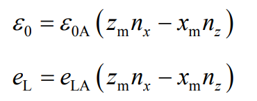
The angular displacement transmission error of no-load large wheel can be obtained by the finite element contact calculation of no-load and loaded hypoid gear ε 0A and the angular displacement transmission error ELA of the loading wheel, the angular displacement transmission error needs to be transformed into the linear displacement transmission error in the action direction of the equivalent meshing force, and the no-load linear displacement transmission error can be obtained respectively ε 0 and load line displacement transmission error el
The equivalent meshing stiffness of hypoid gear is obtained according to the traditional method.
4. Time varying equivalent tangent meshing stiffness
It can be seen from the above analysis that the meshing stiffness obtained by the traditional method formula is the secant stiffness, while the loaded deformation of the actual hypoid gear is a nonlinear process, and the meshing stiffness used in the dynamic calculation should be its tangent meshing stiffness, that is:
Where
Δ F – small variation of equivalent meshing force along the action direction of meshing force when hypoid gear is balanced;
Δδ — Small deformation in the corresponding direction.
Calculation of torque T, t – Δ T and t+ Δ According to the meshing parameters of hypoid gear corresponding to torque T, the tangential stiffness corresponding to torque T is obtained by central difference method.


