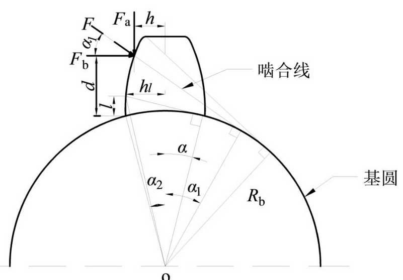
The potential energy method is used to solve the time-varying meshing stiffness of gears.Each tooth is considered as a variable cross-section cantilever beam projecting from the base circle to simulate the deformation of a single tooth under the meshing action of the tooth surface. The meshing force process of the gear is shown in Figure 1.

When the teeth engage, the deformation energy of the teeth mainly consists of the bending potential energy Ub of the teeth, the shear potential energy Us, the radial compression potential Ua and the contact potential Uh of Hertz.The relationship between gear meshing potential U, meshing force F and meshing stiffness K can be expressed by equation (2):
U=F22k (2)
The total engagement stiffness of the gear system can be considered as a series of bending stiffness kb, shear stiffness ks, radial compression stiffness Ka and Hertz contact stiffness kh.The meshing action line of the gear changes constantly during the meshing process, but always engages the tooth profile vertically.Gear meshing force F can be decomposed into two orthogonal forces Fa and Fb.Therefore, the bending stiffness, shear stiffness and radial compression stiffness of the gears can be expressed as (3) – (5) respectively:
1kb=2UbF2=2F2_0d[Fb(d_l)Fah]22EIldl(3)
1ks=2UsF2=2F2_0d1.2Fb22GAldl (4)
1ka=2UaF2=2F2_0dFa22EAldl (5)
Where: Il is the moment of inertia of the gear part at the distance from the root of the gear; Al is the moment of inertia of the effective section; E, G, L and V are respectively expressed as Young’s modulus, shear modulus, tooth width and Poisson’s ratio.Available formulas Il, Al and G (6) – (8) are respectively expressed as:
Il=112(2hl)3L=23hl3L(6)
Al=2hlL (7)
G=E2 (1+_) (8)
The Hertzian contact stiffness of a pair of meshing teeth is constant along the action line [12], independent of the contact position, and can be expressed by formula (9):
Kh=pi EL4(1_v2) (9)
Each tooth of a gear is divided into a single pair of teeth and a double pair of teeth during meshing.The total meshing stiffness of the gears is paralleled by the time-varying meshing stiffness of each pair of engaged teeth and can be expressed by equation (10):
Kt=kt, 1+kt, 2=i=1211kh, i+1kb1, i+1ks1, i+1ka1, i+1kb2, i+1ks2, i+1ka2, i+1ka2, i(10)
Where i=1 is the first pair of teeth and i=2 is the second pair.
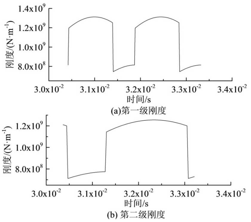
In order to study the change of stiffness under the condition of angular displacement, the line displacement is converted into angular displacement, and the relationship between the time-varying engagement stiffness of gears and the engagement angle is derived. The time-varying engagement stiffness of two-stage gear system is obtained by substituting the gear parameters into equation (3) – (10).
Figure 2 shows the time-varying engagement stiffness of 3.0 x 10⁻²~3.4 x 10⁻² s internal gear system with input shaft rotation frequency of 30 Hz and load of 48.8 N.m.The time-varying meshing stiffness of the gear changes periodically. When the gear pair engages, the gear stiffness gradually increases; when the gear is about to withdraw from the pair engagement, the stiffness gradually decreases; when the gear pair engages with a single pair of teeth, the time-varying stiffness sags and then increases gradually with the engagement stability.

ISO6336-1: In 2006 Calculation of Load Capacity of Spur and Helical Gears standard, the calculation method of maximum and average engagement rigidity of single tooth of gear pair is given, and the engagement rigidity calculated by potential energy method is compared with that calculated by ISO standard.The potential energy method used is in agreement with the stiffness calculated by this standard, which verifies the accuracy of the potential energy method in calculating the stiffness.
