
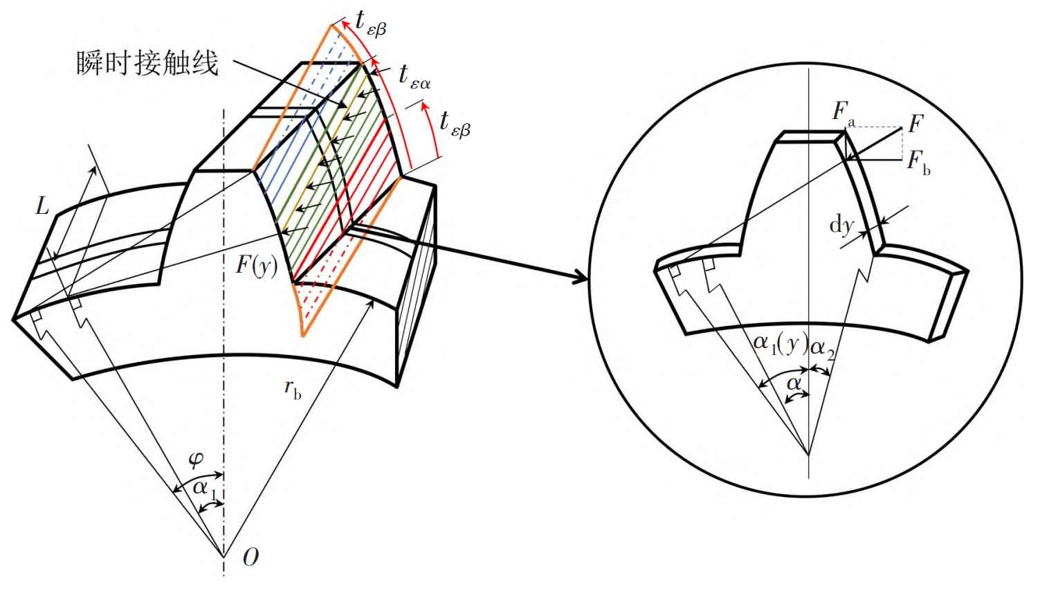
Because of the existence of helical angle, the meshing stiffness of helical gear changes not only with the change of rotation angular displacement, but also with the different positions of the same meshing line at the same time. The helical gear can be divided into a series of slices of equal thickness that are small enough along the axial direction by using the slice method and the integral idea. Each slice is equivalent to a spur gear, as shown in Figure 1. By calculating the meshing stiffness of each spur gear slice, and then integrating, the time-varying meshing stiffness of a helical gear can be obtained.
The time-varying meshing stiffness of spur gears consists of five parts: bending stiffness (kb), shear stiffness (ks), axial compression stiffness (ka), matrix stiffness (k) f and Hertz contact stiffness (kh). The expression of the stiffness of each part is:
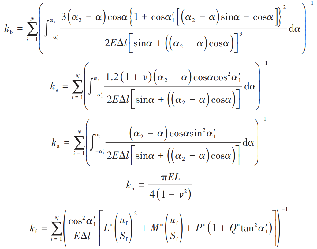
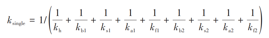
Where, N is the number of slices along the tooth width direction. By treating each stiffness component in parallel, we can get the meshing stiffness of the single tooth meshing with each other as follows:
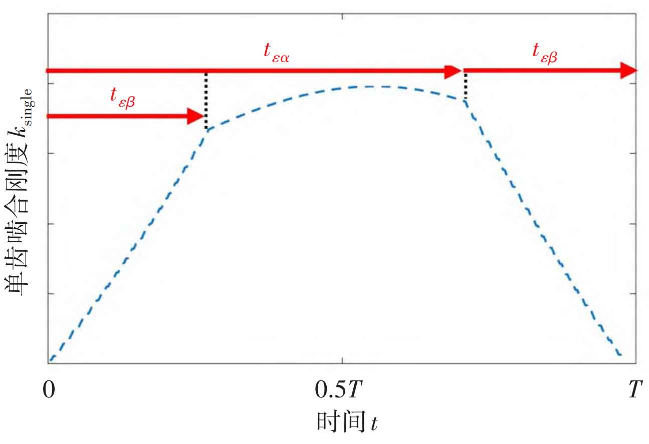
The meshing stiffness change process of a single gear tooth in the complete cycle T from entering engagement to exiting engagement is shown in Figure 2.
For the helical gear system with total coincidence between 2 and 3, there will be two-three-tooth alternating contact during the meshing process. The comprehensive meshing stiffness of the helical gear system is the effect of the joint action of each pair of teeth engaged at the same time, and its change process is shown in Figure 3.
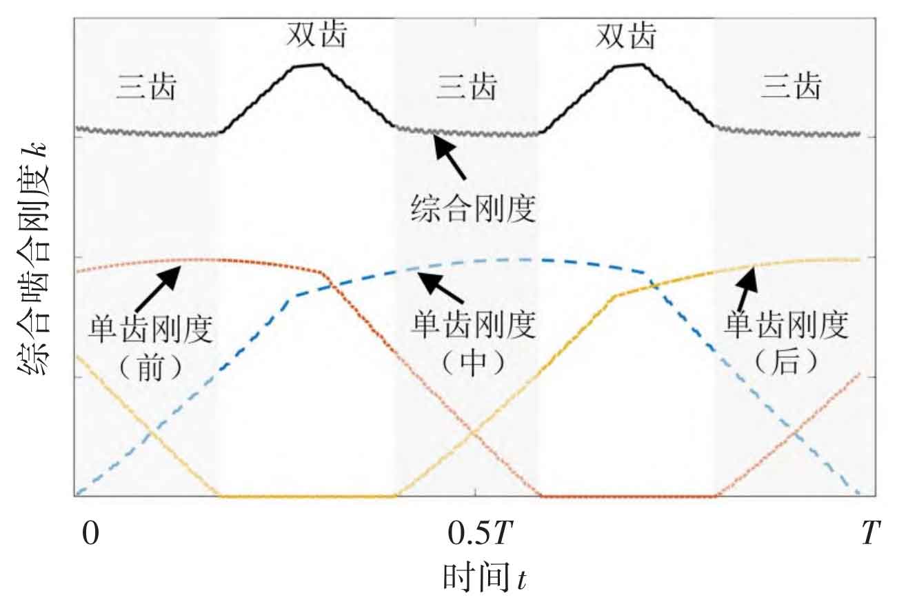
Convert the comprehensive time-varying meshing stiffness k (t) into the form of third harmonic approximately:
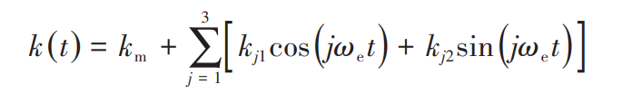
Where, km is the average meshing stiffness, kj1 and kj2 are the harmonic coefficients, ω E is the meshing frequency.