
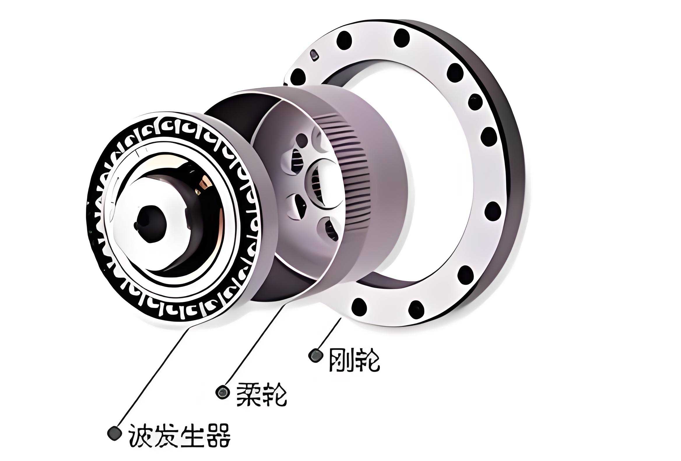
The strain wave gear, also known as a harmonic drive, is renowned for its exceptional capabilities, including high reduction ratios, compact size, lightweight construction, and high positional accuracy. These attributes make it indispensable in demanding fields such as aerospace, robotics, and precision instrumentation. At the heart of its operation lies the flexible spline, or flexspline, which undergoes controlled elastic deformation via a wave generator. This deformation enables multi-tooth meshing, a key feature that distributes load and enhances torque capacity. The design of the tooth profile itself is a critical factor influencing the performance, longevity, and efficiency of the strain wave gear transmission. This article delves into the detailed methodology for designing a conjugate circular-arc tooth profile for the flexspline and circular spline, and subsequently presents an optimization framework aimed at minimizing the meshing backlash to improve transmission precision.
Fundamental Kinematics and the Pitch Curve
The meshing process in a strain wave gear can be conceptualized as the rolling without slip of an elastic curve (the flexspline pitch curve) against a rigid circle (the circular spline pitch circle). Before deformation by the wave generator, the flexspline has a perfect circular pitch circle. Upon the insertion of the wave generator, this circle deforms into a specific closed curve. For a standard elliptical cam wave generator, this deformed neutral curve is approximated as an ellipse.
Let us define the coordinate system. The origin O is at the center of the circular spline. The flexspline’s deformed pitch curve is described in polar coordinates as $\rho = \rho(\phi_1)$, where $\phi_1$ is the angular parameter of a point $A_1$ on this curve. The radii of the circular spline pitch circle and the undeformed flexspline pitch circle are $r_2$ and $r_3$, respectively. The condition of no slip along the arc of contact dictates that the arc lengths traveled on both curves are equal.
The arc length from a starting point to $A_1$ on the flexspline pitch curve is:
$$ L_{A_1} = \int_{0}^{\phi_1} \sqrt{\rho^2 + (\rho’)^2} d\phi $$
where $\rho’ = d\rho/d\phi_1$.
This arc length must equal the corresponding arc length on the circular spline pitch circle, which is $r_2 \phi_2$, and also equal the arc length on the undeformed flexspline pitch circle, $r_3 \phi_3$. Therefore:
$$ \int_{0}^{\phi_1} \sqrt{\rho^2 + (\rho’)^2} d\phi = r_2 \phi_2 = r_3 \phi_3 $$
From this, we derive the relationship between the angles:
$$ \phi_2 = \frac{1}{r_2} \int_{0}^{\phi_1} \sqrt{\rho^2 + (\rho’)^2} d\phi $$
$$ \phi_3 = \frac{1}{r_3} \int_{0}^{\phi_1} \sqrt{\rho^2 + (\rho’)^2} d\phi $$
The instantaneous transmission ratio $i_{32} = \omega_3 / \omega_2$ is then:
$$ i_{32} = \frac{d\phi_3}{d\phi_2} = \frac{r_2}{r_3} $$
This confirms a fundamental kinematic relationship in strain wave gears: the ratio of the pitch circle radii determines the gear reduction ratio.
Flexspline Tooth Profile Generation
The shape of the flexspline tooth must be consistent with the elastic displacements of points on its pitch curve during meshing. For a point $A_1$ on the pitch curve, the deformation caused by the wave generator results in two key displacement components relative to the meshing with the circular spline: the tangential displacement $S_t$ and the normal displacement $S_n$. The locus of points defined by these displacements for all $\phi_1$ generates the flexspline tooth profile.
Geometric analysis yields the following expressions for the displacements at a point defined by $\rho(\phi_1)$ and its derivative:
$$ S_t(\phi_1) = r_2 \sin(\mu + \theta) – \rho \sin \mu $$
$$ S_n(\phi_1) = r_2 \cos(\mu + \theta) – \rho \cos \mu $$
where:
- $\mu = \arctan(\rho’ / \rho)$ is the angle between the radial vector and the normal to the pitch curve.
- $\theta = \phi_1 – \phi_2$ is the angular difference between the flexspline and circular spline parameters for the contacting point.
For an elliptical cam wave generator, the pitch curve is an ellipse with semi-major axis $b$ and semi-minor axis $a$. Its equation is:
$$ \rho(\phi_1) = \frac{ab}{\sqrt{b^2 \sin^2 \phi_1 + a^2 \cos^2 \phi_1}} $$
The semi-axes are related to the nominal geometry. The major axis $b$ equals the flexspline pitch radius plus the maximum radial deformation $\omega_0$: $b = r_3 + \omega_0$. The minor axis $a$ is derived from the condition of constant neutral line length (perimeter of ellipse equals circumference of undeformed pitch circle):
$$ 2\pi r_3 = \int_{0}^{2\pi} \sqrt{\rho^2 + (\rho’)^2} d\phi_1 \approx 2\pi a + 4(b-a) $$
Solving gives:
$$ a = r_3 – \frac{2}{\pi – 2} \omega_0 $$
The derivative $\rho’$ and the angle $\mu$ can be computed directly from the elliptical equation. The integral for $\phi_2$ becomes:
$$ \phi_2 = \frac{1}{r_2} \int_{0}^{\phi_1} \frac{ab \sqrt{b^4 \sin^2 \phi_1 + a^4 \cos^2 \phi_1}}{(b^2 \sin^2 \phi_1 + a^2 \cos^2 \phi_1)^{3/2}} d\phi_1 $$
By evaluating $S_t(\phi_1)$ and $S_n(\phi_1)$ for $\phi_1$ in the range $[0, \pi/2]$ and fitting these coordinate pairs, the discrete points of the flexspline’s circular-arc tooth profile are obtained. A sample of calculated displacements is shown in the table below.
| $\phi_1$ (rad) | $\rho$ (mm) | $\mu$ (rad) | $\theta$ (rad) | $S_t$ (mm) | $S_n$ (mm) |
|---|---|---|---|---|---|
| 0 | 50.875 | 0 | 0 | 0 | 0.2560 |
| $\pi/12$ | 50.779 | -0.014 | 0.0018 | 0.0871 | 0.3532 |
| $\pi/6$ | 50.520 | -0.024 | 0.0061 | 0.2972 | 0.6174 |
| $\pi/4$ | 50.173 | -0.027 | 0.0144 | 0.7103 | 0.9722 |
| $\pi/3$ | 49.833 | -0.023 | 0.0263 | 1.3148 | 1.3109 |
| $5\pi/12$ | 49.586 | -0.013 | 0.0394 | 1.9943 | 1.5314 |
| $\pi/2$ | 49.500 | 0 | 0.0501 | 2.5606 | 1.5668 |
Conjugate Circular Spline Tooth Profile Determination
The circular spline tooth profile is the envelope of the family of curves described by the flexspline tooth profile during the meshing motion. It can be derived using coordinate transformation and the meshing condition.
Two coordinate systems are established:
- System $D_1 (X_1, Y_1, Z_1, O_1)$ is fixed to the flexspline tooth. The origin $O_1$ is at point $A_1$ on the pitch curve, with the $Y_1$-axis aligned along the common normal direction.
- System $D_2 (X_2, Y_2, Z_2, O_2)$ is fixed to the circular spline, with origin $O_2$ at the gear center $O$ and the $Y_2$-axis vertically upward.
In system $D_1$, the circular-arc profile $S_1$ of the flexspline can be parameterized. If the arc has radius $r$, and its center has coordinates $(l_a, X_a)$ relative to $O_1$, a point $M$ on the profile at pressure angle $\alpha_M$ has the position vector:
$$ \mathbf{r}_1 = \begin{bmatrix} r \cos \alpha_M – l_a \\ r \sin \alpha_M – X_a \\ 0 \\ 1 \end{bmatrix} $$
The corresponding unit normal vector at $M$ is:
$$ \mathbf{n}_1 = \begin{bmatrix} \cos \alpha_M \\ \sin \alpha_M \\ 0 \\ 1 \end{bmatrix} $$
The position of this point in the circular spline coordinate system $D_2$ is given by:
$$ \mathbf{r’}_2 = \mathbf{M}_{21} \cdot \mathbf{r}_1 $$
where $\mathbf{M}_{21}$ is the homogeneous transformation matrix from $D_1$ to $D_2$. This matrix is a function of the meshing phase $\phi_1$ and incorporates the rotation and translation between the two systems based on the kinematic relations derived earlier.
For the points to be in contact (i.e., for $\mathbf{r’}_2$ to lie on the envelope), they must satisfy the meshing equation:
$$ \mathbf{n}_1^T \cdot \mathbf{B} \cdot \mathbf{r}_1 = 0 $$
Here, $\mathbf{B}$ is the meshing matrix, which depends solely on the wave generator’s geometry (the form of $\rho(\phi_1)$) and is independent of the specific tooth profile shape. For a given $\phi_1$, solving the meshing equation yields the corresponding pressure angle $\alpha_M$. Substituting this $\alpha_M$ back into the transformation equation $\mathbf{r’}_2 = \mathbf{M}_{21} \cdot \mathbf{r}_1$ provides the coordinates $(x’_2, y’_2)$ of the conjugate point on the circular spline profile. Repeating this process for $\phi_1$ across the meshing range generates a set of discrete points defining the circular spline’s tooth profile, which can then be fitted. A subset of these calculated conjugate points is presented below.
| $\phi_1$ (rad) | $\alpha_M$ (rad) | $x’_2$ (mm) | $y’_2$ (mm) |
|---|---|---|---|
| 0 | 0.000 | -0.20 | 50.778 |
| $\pi/12$ | 1.5385 | 13.65 | 49.392 |
| $\pi/6$ | 1.5342 | 23.37 | 41.230 |
| $\pi/4$ | 1.5270 | 36.04 | 35.260 |
| $\pi/3$ | 1.5370 | 42.26 | 21.340 |
| $5\pi/12$ | 1.5422 | 46.33 | 12.680 |
| $\pi/2$ | 1.5590 | 49.50 | 0.055 |
Mathematical Modeling and Optimization of Meshing Backlash
In precision strain wave gear transmissions, controlling backlash is paramount. Excessive backlash increases positional error and reduces stiffness, while insufficient backlash can lead to binding, increased wear, and efficiency losses. The backlash discussed here refers to the minimum separation between the potential contact surfaces of the flexspline and circular spline teeth in a direction normal to the tooth flank.
Consider two surfaces $S_1$ (flexspline) and $S_2$ (circular spline) in contact at point $M$. The common unit normal vector $\mathbf{n}_1$ points from the material of the flexspline tooth into the void. On the common tangent plane at $M$, choose an arbitrary direction $\alpha$. Let $T_1$ and $T_2$ be the normal sections of $S_1$ and $S_2$ in this direction. Take points $Q_1$ on $T_1$ and $Q_2$ on $T_2$ such that the line $Q_1Q_2$ is parallel to $\mathbf{n}_1$. The distance $d$ between $Q_1$ and $Q_2$ is defined as the normal backlash between the tooth surfaces along the $\alpha$ direction.
Using Taylor expansion and considering the curvature relationship between the conjugate surfaces, the backlash $d$ can be expressed as:
$$ d = \frac{1}{2} K_{12\alpha} \cdot \Delta s_1^2 $$
where $\Delta s_1$ is a small arc length increment from $M$ to $Q_1$ along $T_1$, and $K_{12\alpha}$ is the induced normal curvature of surface $S_2$ relative to $S_1$ in the $\alpha$ direction. For non-interference, we require $K_{12\alpha} \ge 0$. To maximize transmission accuracy and efficiency, we aim to minimize this backlash $d$ subject to practical design constraints.
Applying Willis’ theorem and Euler’s formula for curvature, the induced normal curvature for the strain wave gear pair can be derived in terms of key geometric parameters:
$$ K_{12\alpha} = \frac{\sin \alpha_M \cdot \sin^2(2\mu)}{h} $$
where:
- $\alpha_M$ is the pressure angle at the contact point $M$.
- $\mu$ is the normal rotation angle of the flexspline tooth (equivalent to the angle between the radial vector and the pitch curve normal).
- $h$ is the whole depth of the flexspline tooth profile.
Substituting this into the backlash formula gives the objective function for optimization:
$$ f(\mathbf{X}) = d = \frac{\sin \alpha_M \cdot \sin^2(2\mu)}{2h} \cdot \Delta s_1^2 $$
The design variable vector is therefore:
$$ \mathbf{X} = [\alpha_M, h, \mu, \Delta s_1]^T $$
The optimization seeks to minimize $f(\mathbf{X})$ subject to a set of constraints derived from geometric, kinematic, and manufacturing limits of the strain wave gear:
- Non-interference Condition: $K_{12\alpha} \ge 0 \Rightarrow \dfrac{\sin \alpha_M \cdot \sin^2(2\mu)}{h} \ge 0$. This is typically satisfied for positive pressure angles.
- Meshing Range: $0 \le \phi_1 \le \pi/2$ (for the major axis region of the ellipse).
- Pressure Angle Limit: $\alpha_M \le 25^\circ \approx 5\pi/36$ rad to ensure good force transmission and avoid excessive radial forces.
- Tooth Depth Limit: $h \le 2.2m$, where $m$ is the module, based on standard design practice for circular-arc profiles in strain wave gears to prevent weakening of the flexspline.
- Arc Increment Limit: $0 \le \Delta s_1 \le 0.6$ mm, defining a reasonable small region around the contact point for backlash evaluation.
- Normal Rotation Limit: $\mu \le 0.1$ rad, as the wave generator deformation is relatively small.
Case Study and Optimization Results
To validate the proposed design and optimization methodology, a specific strain wave gear case is analyzed. The key input parameters are:
- Wave Generator: Standard elliptical cam.
- Maximum Radial Deformation, $\omega_0$: 0.5 mm.
- Module, $m$: 0.5.
- Transmission Ratio, $i_{32}$: 1.015.
- Flexspline Pitch Radius, $r_3$: 50.375 mm.
From these, the circular spline pitch radius is $r_2 = r_3 \times i_{32} = 51.131$ mm. The ellipse parameters are calculated as $b = r_3 + \omega_0 = 50.875$ mm and $a = r_3 – \frac{2}{\pi-2} \omega_0 \approx 49.499$ mm. Using the equations from Sections 2 and 3, the conjugate circular-arc profiles for both the flexspline and circular spline are successfully generated.
For the backlash optimization, the nonlinear constrained problem defined by the objective function $f(\mathbf{X})$ and the constraints is solved numerically using an appropriate algorithm (e.g., sequential quadratic programming). The initial tooth profile parameters from the design phase serve as a starting point. The optimization converges to the following optimal set of design variables:
| Design Variable | Symbol | Optimal Value |
|---|---|---|
| Pressure Angle at Contact Point | $\alpha_M$ | 0.165 rad (~9.45°) |
| Whole Depth of Tooth Profile | $h$ | 0.686 mm |
| Normal Rotation Angle of Tooth | $\mu$ | 0.009 rad |
| Arc Length Increment on Contact Line | $\Delta s_1$ | 0.725 mm |
With this optimal configuration, the minimized normal backlash is:
$$ d_{min} = f(\mathbf{X}_{opt}) \approx 1.88 \times 10^{-5} \text{ mm} $$
This extremely small value, achieved while satisfying all geometric constraints, demonstrates the effectiveness of the optimization model in virtually eliminating clearance between the conjugate circular-arc profiles, thereby promising high positional accuracy for the strain wave gear assembly.
Conclusion
This article has presented a comprehensive methodology for the design and optimization of circular-arc tooth profiles in strain wave gear drives. The process begins with the kinematic analysis of the deformed flexspline pitch curve, leading to the calculation of the specific tangential and normal displacements that define the flexspline tooth geometry. Through coordinate transformation and the application of the meshing condition, the conjugate profile for the circular spline is precisely determined. The core contribution lies in the development of a quantitative backlash model based on surface curvature theory, which is then formulated as an optimization problem. By strategically selecting the pressure angle, tooth depth, normal rotation angle, and a contact line increment as design variables, and imposing practical engineering constraints, the meshing backlash can be minimized effectively. A detailed case study for an elliptical cam wave generator confirms the validity of the theoretical models. The resulting optimal parameters provide a clear guide for designing high-precision, low-backlash strain wave gear transmissions with circular-arc teeth, enhancing their performance in critical applications where precision and reliability are paramount. The principles outlined here form a solid foundation for the advanced design of this sophisticated and essential mechanical component.