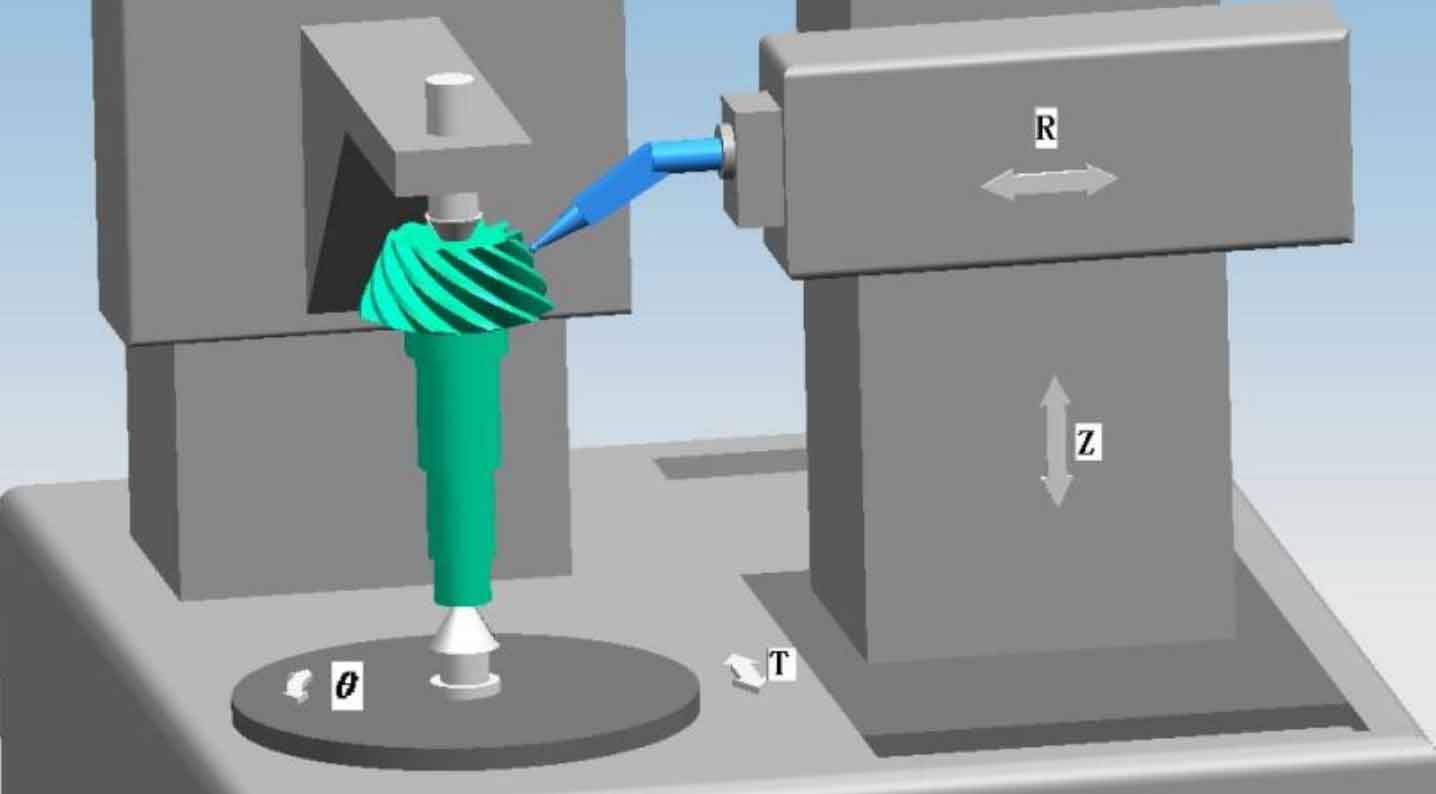
The tooth profile of spiral bevel gear is a complex free-form surface. At present, its measurement is mainly carried out on the spiral bevel gear measurement center. Spiral bevel gear measuring center is a coordinate measuring system with four axis linkage, as shown in Figure 1.
① Installation and positioning of spiral bevel gear and calibration of probe
Install the measured spiral bevel gear on the rotary table. Axial spiral bevel gears are generally positioned by the center, while disk spiral bevel gears are generally positioned by high-precision three jaw chuck or equal height block. When positioning, align the spiral bevel gear journal or inner hole so that its axis is consistent with the rotating shaft of the spiral bevel gear measuring center θ Coaxial. Firstly, calibrate the probe and establish the measurement coordinate system. At present, domestic spiral bevel gear measurement centers mostly use one-dimensional inductive probe, which can only feel the deformation in one direction. Therefore, the calibration of probe should be carried out in two steps: the calibration of probe is carried out with the help of standard ball. Firstly, calibrate the RT direction, adjust the force on the probe in the T direction, and install the standard mandrel on the center of the measurement center.
Manually control the R, t and Z axes of the spiral bevel gear measuring center so that the measuring head is directly in front of the standard ball, and collect the coordinates of 6 points in the RT plane of the standard ball to fit the center of the standard ball; Then control the probe to collect 6 point coordinates on the mandrel and fit them θ Axis coordinates, then the difference between the two RT directions is from the center of the standard ball to θ The distance in the RT direction of the axis. Then conduct Z-direction calibration and adjust the probe to Z-direction force. Manually control so that the center of the probe is directly above the standard ball, and collect the coordinates of 6 points in the RZ plane on the standard ball to fit the center of the standard ball; Then control the probe to detect the spiral bevel gear installation base surface, and calculate the distance from the center of the standard ball to the spiral bevel gear installation base surface along the Z axis. In actual use, the installation distance of spiral bevel gear should also be added, so that the measurement coordinate system is located at the staggered intersection of spiral bevel gear.
② Mesh generation of theoretical tooth surface measurement based on full NC machining method
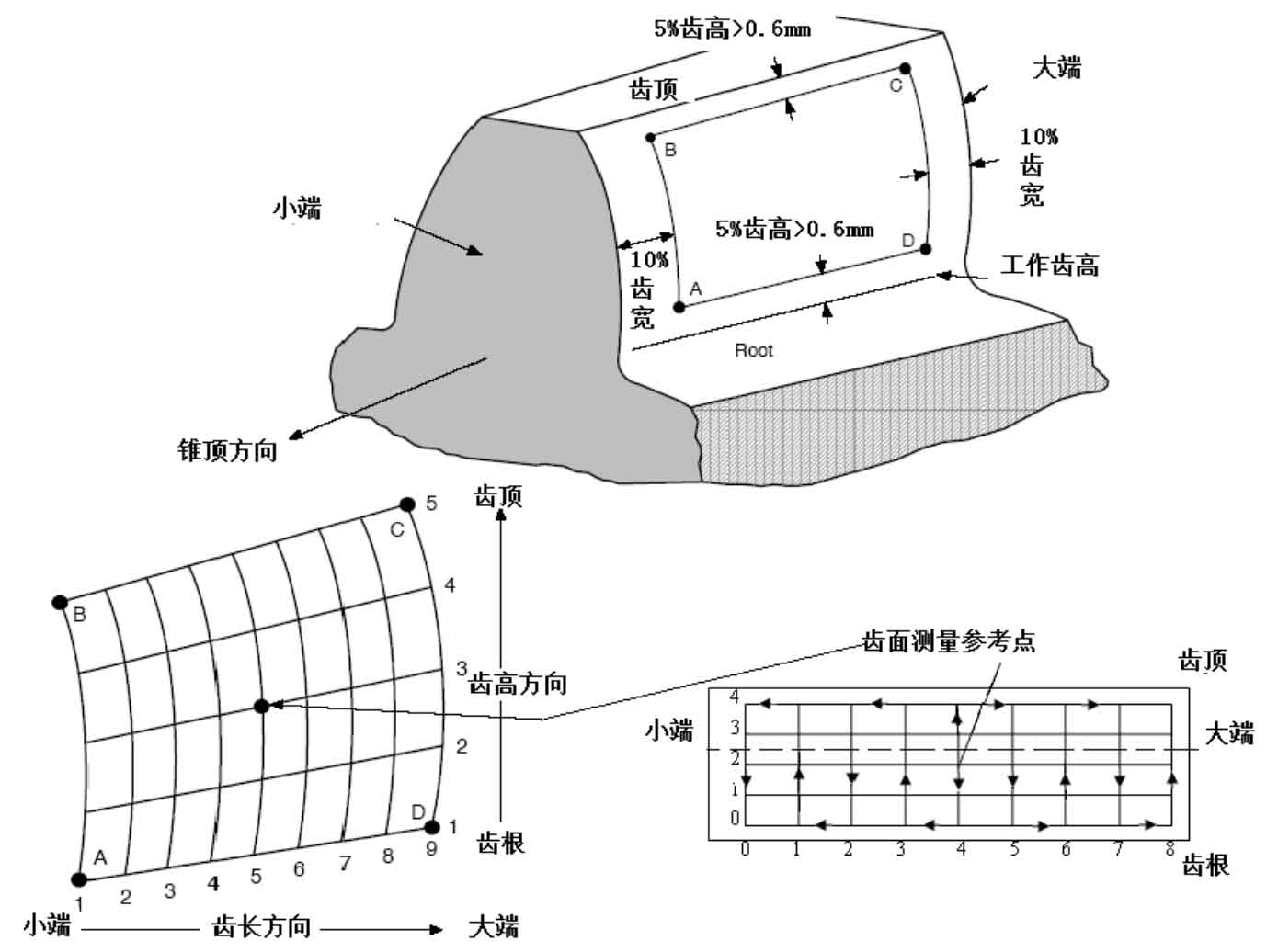
The geometry of spiral bevel gear tooth surface can be indirectly represented by a series of grid coordinates on the tooth surface, as shown in Figure 2. In order to avoid the probe exceeding the tooth surface range or interfering with the tooth root during measurement, it is necessary to shrink the tooth surface measurement range appropriately, and then divide the tooth length and tooth height direction of spiral bevel gear into grids evenly in the contraction area, usually 9 grid points in the tooth width direction and 5 grid points in the tooth height direction. Because the mesh generation on the surface is not easy, it can be transformed into the two-dimensional coordinate system of the shaft section of spiral bevel gear, and the geometric parameters of the tooth blank of spiral bevel gear can be used for mesh generation. After the meshing in the shaft section, based on the tooth profile generation motion of full NC face hobbing, it is calculated into the mesh coordinates on the tooth surface by using the conjugate surface principle.