
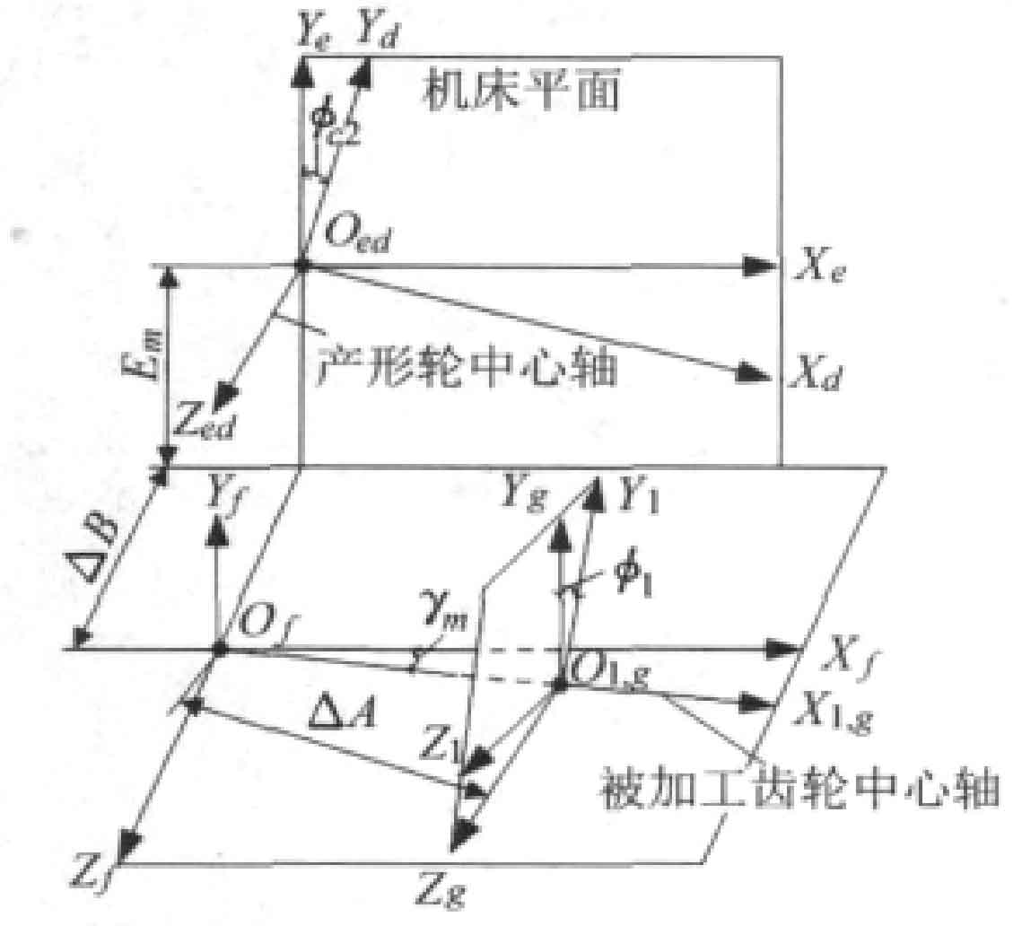
In the process of generating, the wheel blank and the forming wheel are hobbed to form a cycloid hypoid gear. The figure shows the developed coordinate system of the tooth surface, S1 is the coordinate system fixedly connected with the processed gear, and Se, SF and SG are the auxiliary coordinate system. The tooth surface equation is:

Of which:
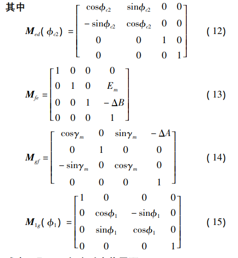
Where
Em — vertical offset distance of machine tool
Δ B — feed rate of sliding seat
Φ C2 — driven angle of shaking table
Δ A — travel from machine center to rear seat
γ M — root cone angle of machine tool
Φ 1 – angle of machined gear
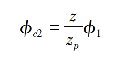
Driven angle of shaking table Φ C2 and angle of machined gear Φ The relationship between 1 is:
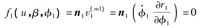
In the meshing process between the forming wheel and the wheel blank, there is an meshing equation in the S1 coordinate system:
Where:
V (M1) 1 – the relative speed of the cutting edge and the machined gear in the coordinate system S1
N1 — unit normal vector of tooth surface
The tooth surface equation can be solved according to the formula. Then do the rotation projection surface through the gear shaft section, mesh the tooth surface, and get the tooth surface simulation model.