
Gear honing, specifically internal gear honing, is a critical finishing process in the manufacturing of high-precision gears for automotive transmissions and other demanding applications. As a finishing operation performed after heat treatment, it is designed to improve gear quality by correcting geometrical deviations, enhancing surface finish, and inducing favorable residual stresses. Among various honing techniques, power honing with an internal honing wheel stands out due to its high material removal rate and superior corrective capabilities stemming from the large contact area and high overlap ratio inherent in internal meshing. However, a persistent challenge in this process is the unintended phenomenon of “root digging” or “tooth root over-honing,” where excessive material is removed from the dedendum region of the workpiece gear. This not only alters the ideal involute profile but can also negatively impact the bending strength and meshing performance of the gear. Therefore, a thorough understanding of the root causes of this phenomenon is essential for optimizing the gear honing process and achieving consistent, high-quality results. This article delves into the fundamental mechanisms behind tooth surface root digging during numerical control (NC) power gear honing with an internal honing wheel, analyzing it from the perspectives of honing pressure distribution and relative sliding velocity at the tooth contact interface.
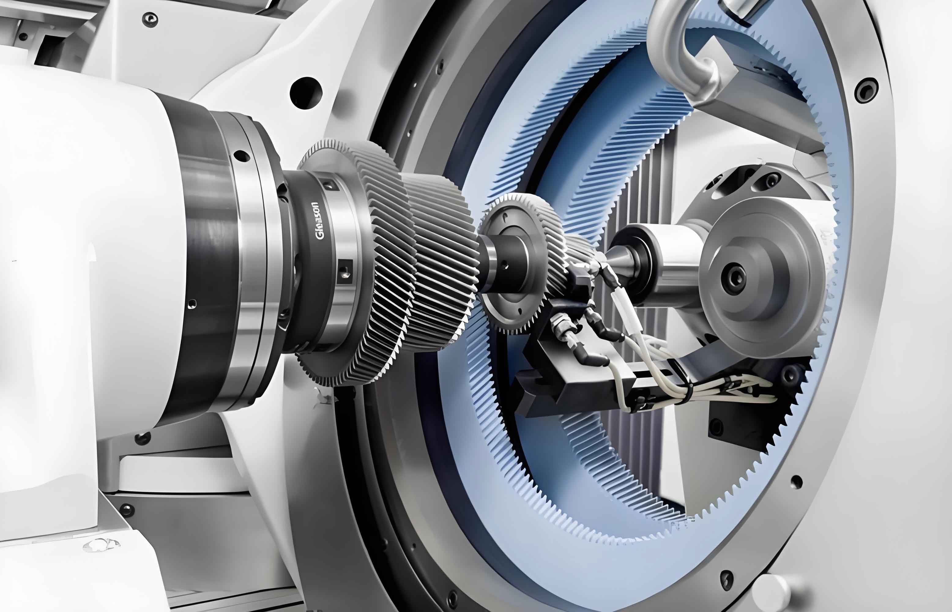
1. Introduction to Internal Gear Honing Process
Power gear honing is an abrasive machining process where a gear-shaped tool, the honing wheel, meshes with the workpiece gear under controlled conditions of force, speed, and crossed axes. The honing wheel is typically made of a phenolic resin or metal bond impregnated with abrasive grains such as aluminum oxide (Al2O3) or cubic boron nitride (CBN). In the internal variant, the honing wheel is an internal gear, and the workpiece is an external gear. The axes of the honing wheel and the workpiece are set at a small crossed-axes angle (Σ). This angle, combined with the differential rotational speeds, generates a sliding motion along the tooth flanks, which is the primary mechanism for material removal. The NC system precisely controls the rotational motions (ωh, ωw) and the radial infeed to achieve the desired stock removal and profile modification.
The advantages of internal gear honing over external gear honing are significant. The internal meshing configuration offers a larger contact area and a higher contact ratio. This leads to more cutting edges being engaged simultaneously, distributing the load and improving the correction of pitch errors and profile deviations. The process is highly efficient for hard-finishing gears after carburizing and hardening, often simplifying the production chain by eliminating preliminary grinding operations. Despite these benefits, controlling the final tooth profile, particularly preventing over-honing at the root, remains a key challenge in gear honing process design.
2. Analysis of Honing Pressure Distribution on the Tooth Flank
The material removal in gear honing is the cumulative result of micro-cutting actions by countless abrasive grains on the honing wheel’s surface. To understand the non-uniform stock removal that leads to root digging, we must first examine the distribution of cutting forces, specifically the normal force (honning pressure), across the tooth flank from the tip to the root.
2.1. Mechanical Model of Single Abrasive Grain Cutting
The cutting action can be modeled starting from a single abrasive grain. Considering a grain as a sharp, conical indenter, the forces during micro-cutting can be decomposed into tangential (Ft), normal (Fn), and axial (Fa) components. The axial component is often negligible. Based on grinding mechanics, the force components for a single grain can be expressed as:
$$ F_t = k p \left( \frac{a_p v_w b}{v_h} \right) + \mu F_n $$
$$ F_n = k p \left( \frac{\pi a_p v_w b}{v_h} \right) \tan \frac{\beta}{2} $$
where:
k is a coefficient related to the undeformed chip cross-section area,
p is the contact interface pressure,
ap is the depth of cut (grain penetration),
vw is the workpiece surface speed,
vh is the honing wheel surface speed,
b is the honing width,
μ is the friction coefficient, and
β is the apex angle of the abrasive grain cutting edge.
The normal force Fn is of primary interest as it directly relates to the contact pressure between the grain and the workpiece, influencing plastic deformation, chip formation, and ultimately, the rate of material removal in gear honing.
2.2. Relationship with Gear Meshing Sliding Ratio
In gear meshing, sliding occurs between the contacting flanks. The sliding ratio (or specific sliding) η quantifies this relative motion. For a point of contact on the workpiece flank, the sliding ratio ηw is defined as the relative difference in the arc lengths traveled by the two contacting points on the workpiece and the tool. For involute gears, it can be derived as a function of the operating pressure angles at the contact point.
Let α1 and α2 be the pressure angles at the contact point for the workpiece and honing wheel, respectively. The sliding ratios are:
$$ \eta_w = 1 – \frac{\tan \alpha_2}{\tan \alpha_1} \quad \text{(for workpiece addendum)} $$
$$ \eta_h = 1 – \frac{\tan \alpha_1}{\tan \alpha_2} \quad \text{(for honing wheel dedendum)} $$
During the honing cycle, a point on the workpiece tooth flank experiences varying sliding conditions as the contact point moves from the tip to the root. The relative motion dLw/dLh between the flanks is intrinsically linked to this sliding ratio. By relating the kinematic differentials of the contacting arc lengths to the sliding ratio, we can reformulate the normal force equation. Starting from Fn:
$$ F_n = k p \left( \frac{\pi a_p b \cdot v_w \cdot dt}{v_h \cdot dt} \right) \tan \frac{\beta}{2} = k p \pi a_p b \left( \frac{dL_w}{dL_h} \right) \tan \frac{\beta}{2} $$
Through kinematic analysis of the internal meshing, it can be shown that the ratio dLw/dLh is related to the sliding ratio ηh of the honing wheel (or ηw of the workpiece). Therefore, the normal cutting force for a single grain acting on the workpiece flank can be expressed as a function of the sliding ratio:
$$ F_n = Q \cdot (1 – \eta_h) \quad \text{or alternately} \quad F_n = Q \cdot \frac{1}{1 – \eta_w} $$
where \( Q = k p \pi a_p b \tan(\beta/2) \) is assumed to be constant for a given set of process parameters at a given moment in time during gear honing.
This relationship is crucial. It indicates that the local honing pressure (proportional to Fn) is not constant across the tooth profile but varies with the sliding ratio. In internal gear honing, the sliding ratio ηh is not constant along the path of contact. It typically has a larger magnitude in the dedendum (root) region of the workpiece compared to the addendum (tip) region. According to the equation Fn = Q(1 – ηh), a larger magnitude of ηh (which is negative in internal meshing for the honing wheel’s dedendum) results in a larger value for (1 – ηh), and consequently, a larger normal force Fn.
2.3. Theoretical Pressure Distribution and Finite Element Validation
Based on the derived model, the normal force (and thus the honing pressure) is lowest at the tooth tip (point B1), increases at the pitch point (P), and reaches its maximum at the tooth root (point B2). The pressure in the root region can be more than twice that at the tip. This non-uniform pressure distribution directly suggests that the abrasive grains experience higher loads and are likely to remove more material per unit time in the root area, leading to the root digging phenomenon in gear honing.
To validate this theoretical pressure distribution, a three-dimensional Finite Element Analysis (FEA) can be performed. A model of an internal gear pair, representing the honing wheel and workpiece, is constructed. A radial load is applied to the workpiece gear center to simulate the honing force. The analysis focuses on the contact stress distribution on the workpiece tooth flank.
| Gear Parameter | Workpiece (External) | Honing Wheel (Internal) |
|---|---|---|
| Normal Module (mn) | 2.25 mm | 2.25 mm |
| Normal Pressure Angle (αn) | 17.5° | 17.5° |
| Helix Angle (β) | 33° | 41.722° |
| Number of Teeth (z) | 73 | 123 |
| Face Width (b) | 27 mm | 32 mm |
| Crossed-Axes Angle (Σ = |βh – βw|) | 8.722° | |
The FEA results consistently show that the maximum contact stress (von Mises stress) occurs at the root region of the workpiece tooth. The stress at the pitch line area is lower, and the tip region experiences the least stress. This pattern conclusively supports the theoretical model derived from single-grain cutting mechanics. The higher stress at the root correlates with higher honing pressure, providing a clear mechanistic explanation for preferential material removal and root digging during the gear honing process.
3. Analysis of Relative Sliding Velocity Distribution
While honing pressure is a primary factor, the relative sliding velocity between the honing wheel and workpiece tooth flanks is another critical parameter governing material removal rate in gear honing. The stock removal in abrasive processes is often related to the specific energy and the sliding distance. A non-uniform velocity distribution can lead to non-uniform wear or cutting action.
3.1. Mathematical Model of Tooth Surface Contact
To analyze the relative velocity, we establish the coordinate systems for the internal gear honing process. Let S(O-xyz) be the fixed frame connected to the workpiece, and Sp(Op-xpypzp) be the fixed frame connected to the honing wheel. Their origins are separated by the center distance, a. The z-axes represent the axes of rotation, and they are crossed at an angle γ (the shaft angle). The workpiece rotates by angle φ1 with angular velocity ω1, and the honing wheel rotates by angle φ2 with angular velocity ω2, maintaining a constant gear ratio i12 = ω1/ω2 = zh/zw.
The surface of the workpiece gear can be represented as an involute helicoid:
$$
\begin{aligned}
x &= r_b \cos(\sigma_0 + u + \theta) + r_b u \sin(\sigma_0 + u + \theta) \\
y &= r_b \sin(\sigma_0 + u + \theta) – r_b u \cos(\sigma_0 + u + \theta) \\
z &= p \theta
\end{aligned}
$$
where rb is the base radius, σ0 is the start angle of the involute, u and θ are surface parameters, and p is the helix parameter.
The relative velocity v(12) at a contact point M between surface 1 (workpiece) and surface 2 (honing wheel) is given by:
$$ \mathbf{v}^{(12)} = \mathbf{v}^{(1)} – \mathbf{v}^{(2)} = \boldsymbol{\omega}^{(1)} \times \mathbf{r}^{(1)} – \boldsymbol{\omega}^{(2)} \times \mathbf{r}^{(2)} $$
By applying coordinate transformations from the workpiece coordinate system S1 to the fixed frame S, the components of the relative velocity at the contact point can be derived. After extensive algebraic manipulation, the relative velocity vector in the workpiece coordinate system can be expressed as a function of the mesh parameters and the position on the tooth flank (through parameter τ = σ0 + u + θ + φ1):
$$
\mathbf{v}_M^{(12)} = \omega_1
\begin{bmatrix}
r_{b1}(\sin \tau – u \cos \tau)(\cos\gamma / i_{12} – 1) \\
r_{b1}(\cos \tau + u \sin \tau)(1 – \cos\gamma / i_{12}) – a \cos\gamma / i_{12} \\
-r_{b1}(\cos \tau + u \sin \tau)\sin\gamma / i_{12} – a \sin\gamma / i_{12}
\end{bmatrix}
$$
3.2. Velocity Distribution along the Tooth Profile
The magnitude of the relative sliding velocity, particularly its component tangent to the tooth profile, is of interest. By evaluating the above equation for points along the transverse section of the workpiece tooth (setting θ=0 to analyze the transverse profile), we can plot the relative sliding speed against the roll angle or the position from the root to the tip.
For the gear parameters listed in Table 1 and a typical honing wheel speed (e.g., nh = 860 rpm), the analysis reveals a distinct pattern. The relative sliding speed is not constant along the profile. It reaches its maximum value in the dedendum (root) region of the workpiece gear. The speed is lower in the addendum (tip) region and often minimum around the pitch line area. This distribution is a direct consequence of the kinematics of internal crossed-axes meshing combined with the involute tooth geometry.
The higher relative sliding velocity at the tooth root means that, for a constant honing time, the abrasive grains travel a longer sliding distance over the root area compared to the tip area. Even if the pressure were constant, this would lead to more cumulative abrasive work and thus more material removal at the root. When combined with the previously established higher honing pressure at the root, the effect is synergistic and strongly promotes the root digging phenomenon in gear honing.
3.3. Comparison: Internal vs. External Gear Honing
It is instructive to compare the relative velocity distribution for internal gear honing with that of external gear honing under similar conditions. The kinematic equations for external honing differ, leading to a different velocity profile. Analysis shows that the gradient of relative sliding speed from root to tip is generally more pronounced in external honing. This implies that the tendency for non-uniform stock removal, potentially causing both root digging and tip relief, is more acute in external gear honing. The internal honing configuration, by virtue of its kinematics, offers a somewhat more favorable (flatter) distribution of relative velocity, making it slightly less prone to extreme profile errors, though root digging remains a significant concern that must be actively managed.
4. Experimental Verification and Process Implications
The theoretical analyses point to two main culprits for root digging in gear honing: high localized honing pressure and high relative sliding speed at the tooth root. These insights lead directly to practical strategies for mitigating the problem. The core idea is to modify the process conditions to either flatten the pressure distribution or compensate for the velocity-induced over-honing.
4.1. Experimental Setup and Methods
Experiments were conducted on a precision CNC gear honing machine (e.g., a Faessler HMX-400 type). The honing wheel was made with Al2O3 abrasives, and the workpiece gears were made of 20CrMnTiH, case-hardened. Two distinct power honing strategies were employed to validate the influence of process parameters:
Method 1: Constant Center Distance, Variable Pressure Honing. This is a common traditional approach. The honing wheel is fed radially to a predetermined center distance to achieve the target stock removal. Once the final position is reached, the center distance is fixed, and honing continues for a set number of strokes or time. In this phase, as material is removed, the actual contact pressure between the gears decreases.
Method 2: Variable Center Distance, Constant Pressure Honing. This is a more advanced, controlled process. The honing wheel is continuously fed radially inward during the honing cycle. The NC system adjusts the infeed rate to maintain a relatively constant normal force or torque between the two gears throughout the material removal process.
After honing, individual teeth were sectioned from the workpiece gears for detailed examination of the flank topography using an optical measuring instrument (e.g., a JVL250 vision system).
| Feature | Method 1: Const. Center Distance | Method 2: Variable Center Distance |
|---|---|---|
| Radial Infeed | Intermittent, then fixed | Continuous, controlled |
| Honing Pressure | High initially, decays over time | Actively maintained near constant |
| Kinematic Conditions | Constant | Constant |
| Root Digging Tendency | High (Observed) | Low (Observed) |
| Key Principle | Fixed geometry leads to peak root pressure at the start of the finishing stroke. | Constant pressure avoids extreme localized loading, allowing more uniform wear. |
4.2. Results and Discussion
The experimental observations strongly support the theoretical mechanisms. Gears honed using Method 1 showed clear evidence of root digging. The optical profile images revealed a noticeable deviation from the ideal involute profile in the dedendum region, where material was excessively removed. This aligns with the theory: at the fixed center distance, the initial contact and highest interference occur, generating maximum honing pressure. According to the Fn distribution model, this pressure is concentrated at the root. Furthermore, the root also experiences the highest sliding velocity. The combination leads to rapid material removal at the root at the beginning of the cycle, creating the dug profile.
In contrast, gears honed using Method 2 exhibited a significantly improved tooth profile. The root digging was minimal or absent, and the involute profile was preserved much more accurately. The controlled, constant-pressure approach prevents the intense localized loading at the root. While the relative velocity distribution remains unchanged, the reduced and steady pressure mitigates its negative effect, leading to a more uniform material removal across the flank during the gear honing process.
These results underscore a critical practical conclusion: the radial infeed strategy is paramount in controlling root digging. A variable center distance strategy aimed at constant honing force is far superior to a simple fixed-position strategy. Additionally, other parameters can be optimized. For instance, adjusting the crossed-axes angle (γ) can modify the sliding velocity distribution. Using honing wheels with a tailored abrasive density or a specific lead crowning can also help redistribute the honing pressure more evenly. Modern CNC gear honing machines allow for sophisticated “modified roll” kinematics, where the gear ratio i12 is varied slightly during the roll, effectively changing the instantaneous contact points and sliding conditions to achieve a desired final profile, including the prevention of root digging.
5. Conclusion
Root digging in NC power gear honing with an internal honing wheel is a complex phenomenon rooted in the fundamental kinematics and mechanics of the abrasive process. Through detailed analysis, two primary and interlinked mechanisms have been identified:
- Non-uniform Honing Pressure: Derived from single-grain cutting mechanics and gear mesh kinematics, the normal force (pressure) on the abrasive grains is highest at the tooth root of the workpiece. This is fundamentally linked to the sliding ratio, which varies along the path of contact. Finite Element Analysis confirms this stress concentration at the root.
- Non-uniform Relative Sliding Velocity: The kinematic analysis of internal crossed-axes meshing shows that the magnitude of the relative sliding velocity between the flanks is also maximum in the tooth root region. This results in a longer effective cutting path and greater cumulative abrasive work per unit time in the dedendum.
The synergy of high pressure and high sliding velocity at the root creates a strong propensity for localized over-honing, manifesting as root digging. Experimental validation comparing constant center distance and variable center distance (constant pressure) honing strategies confirms these findings. The constant-pressure approach effectively mitigates root digging by avoiding the peak loads associated with a fixed geometry.
Therefore, to control and prevent root digging in industrial gear honing applications, process designers should prioritize strategies that manage the interfacial pressure distribution. This includes implementing controlled radial infeed cycles for constant force, optimizing the crossed-axes angle, and leveraging advanced CNC capabilities for kinematic modifications. A deep understanding of these mechanisms is essential for harnessing the full potential of internal gear honing as a high-precision, efficient, and reliable hard-finishing technology.