
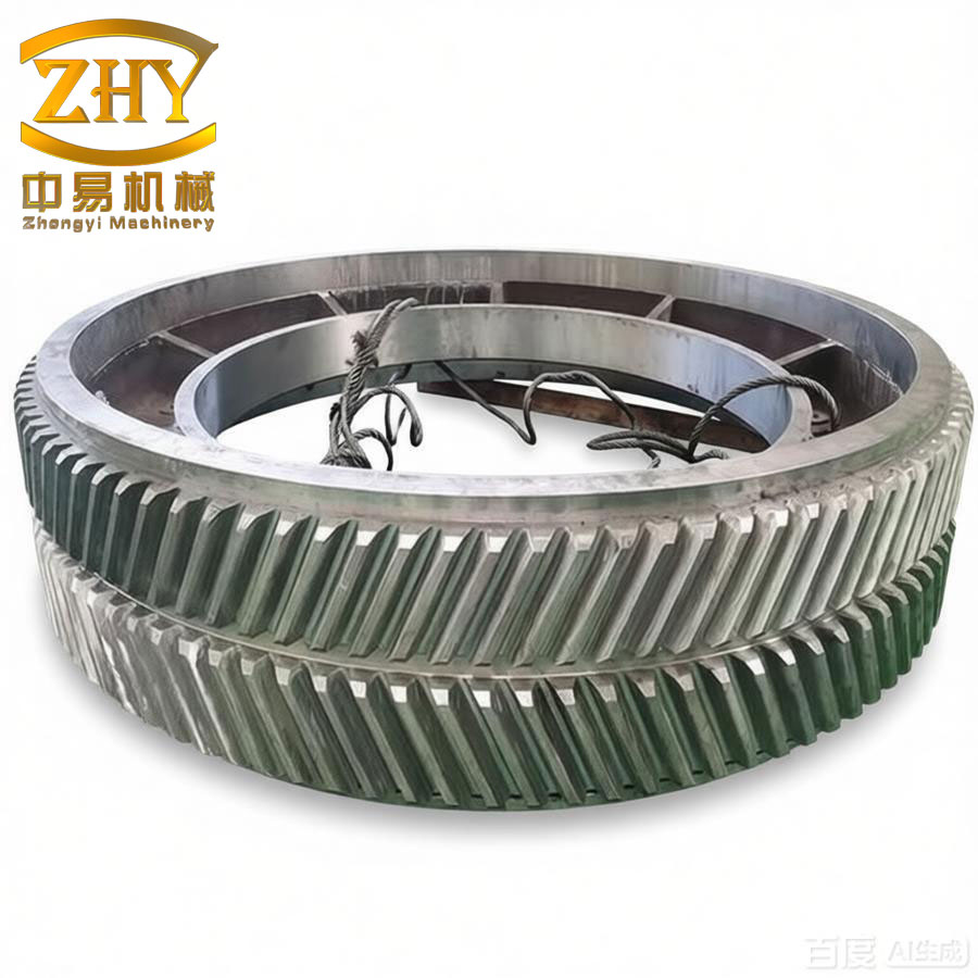
Herringbone gears are dual-helical cylindrical gears composed of two symmetric helical gear halves with opposite helix directions. They inherently cancel axial thrust forces and achieve high contact ratios, making them indispensable in high-speed, heavy-load transmission systems used in aviation, marine, and industrial applications. However, these operating conditions expose herringbone gears to contact fatigue, scoring, and adhesive wear. To mitigate such failures, tooth surface modification is a key enabler. While conventional modification methods such as profile and lead crowning are well-established for spur gears, their direct application to herringbone gears is problematic because the contact lines of helical flanks are inclined relative to the gear axis, making the meshing process fundamentally different from that of spur gears. In this thesis, I develop a topology modification design framework that explicitly accounts for the meshing characteristics of herringbone gears. The proposed method enables precise control of the meshing process, improves load distribution, and reduces maximum contact stress. I further extend the methodology to system-level optimization of an aviation split-torque transmission, and verify manufacturability through five-axis CNC form grinding experiments. The results confirm that the proposed topology modification method lowers the simulated contact stress by about 15% compared with conventional modification, while preserving the overlap ratio and yielding a centralized, elliptical contact pattern. This work provides a practical and effective design-to-manufacturing solution for high-performance herringbone gears.
1. Introduction
Gear transmissions are fundamental mechanical components in modern industry, and their performance directly governs the reliability, efficiency, and service life of rotating machinery. Among the various gear types, herringbone gears occupy a unique niche because of their ability to transmit large torques at high speeds while eliminating axial bearing loads. The double-helical configuration doubles the effective face width of engagement, yielding a high contact ratio and smooth load transfer. In the aerospace sector, herringbone gears are used in main rotor transmissions, accessory gearboxes, and split-torque systems where weight, reliability, and load-sharing are critical. In such demanding environments, tooth surface damage modes, particularly scuffing, micropitting, and contact fatigue, are the primary failure mechanisms. Designers therefore rely on tooth surface modification to alter the local geometry, redistribute contact pressure, and accommodate elastic deflections and assembly misalignments.
Traditional modification methods are based on profile modification and lead modification. Profile modification removes material near the tooth tip or root to reduce mesh-in and mesh-out shocks, while lead modification introduces a crowning along the face width to reduce edge loading caused by shaft deflections and bearing clearances. These methods were originally developed for spur gears, where the contact lines are straight lines parallel to the gear axis. For helical tooth flanks, however, the contact line is a helix tangent to the base cylinder. When profile and lead modifications are applied to helical gears, the effects on the contact pattern are coupled and difficult to predict. This coupling becomes even more severe for herringbone gears because of the large helix angles commonly used to maximize the contact ratio. Diagonal modification is a partial solution that removes material at two diagonally opposite regions of the flank to ease mesh entry and exit, but it does not address edge loading along the contact lines.
Topological modification provides a more flexible approach: the entire tooth surface is defined by a grid of normal deviations, and the modification amount can be tailored at every surface point. However, a fully arbitrary topology is not necessarily manufacturable, and the design space is too large for practical engineering. A compact parametric representation is therefore required. In this thesis, I adopt a second-order polynomial representation of the ease-off surface with five independent parameters, and I introduce a coordinate transformation that aligns the ease-off surface with the instantaneous contact lines of the gear pair. This allows me to design the modification along the contact-line direction and the meshing direction separately. The result is a topology modification method that can independently control the number and length of active contact lines during meshing, which is not achievable with conventional profile-plus-lead modification.
The remainder of this thesis is organized as follows. Section 2 derives the theoretical tooth surface of herringbone gears, analyses the meshing characteristics, and presents the proposed topology modification design method together with a comparative finite element study. Section 3 describes the system-level finite element modelling of a herringbone gear split-torque transmission, introduces a parametric modelling technique based on automatic mesh generation and Abaqus secondary development, and presents an optimization workflow that uses parallel computing. Section 4 investigates the manufacturing side: I derive the disc wheel profile from the theoretical flank, formulate the five-axis grinding kinematics, and demonstrate how higher-order synchronous motion of the machine axes can generate the designed topological tooth surface. Section 5 describes machining experiments and contact pattern verification, and Section 6 concludes the thesis.
2. Topological Modification Design of Herringbone Gear Pairs Considering Meshing Characteristics
In this section, I first derive the mathematical equation of the theoretical involute helical tooth surface of herringbone gears. I then analyse the meshing process and identify the key issues of conventional modification methods. Based on these insights, I propose a new topology modification method that uses a five-parameter second-order ease-off surface expressed in a coordinate system aligned with the contact lines. Finally, I verify the method through a comparative finite element contact analysis of a herringbone gear pair under different modification strategies.
2.1 Theoretical Tooth Surface of Herringbone Gears
A herringbone gear is a symmetric assembly of two helical gears with equal and opposite helix angles. Its flank geometry is therefore the same as that of a helical gear. The involute helical surface can be generated by a planar involute curve that performs a helical motion along the gear axis. In the coordinate system \(S_a(x_a,y_a,z_a)\) fixed to the gear, we define the planar involute profile as
\[
x_a = r_b (\varphi_1 \sin\varphi_1 + \varphi_1 \cos\varphi_1), \quad y_a = r_b (\varphi_1 \cos\varphi_1 – \varphi_1 \sin\varphi_1), \quad z_a = 0,
\]
where \(r_b\) is the base radius and \(\varphi_1\) is the roll angle parameter. The helical generation is described by a screw motion with parameter \(p\) along the axis, i.e. the axial translation per unit rotation. Introducing the face-width coordinate \(u = p\psi\), where \(\psi\) is the rotation angle of the helical sweep, the complete tooth surface in the gear coordinate system \(S_1(x_1,y_1,z_1)\) can be written as
\[
\mathbf{r}_1(\varphi_1,u) = \begin{bmatrix} \cos(u/p) & -\sin(u/p) & 0 & 0 \\ \sin(u/p) & \cos(u/p) & 0 & 0 \\ 0 & 0 & 1 & 0 \\ 0 & 0 & 0 & 1 \end{bmatrix} \begin{bmatrix} x_a(\varphi_1) \\ y_a(\varphi_1) \\ 0 \\ 1 \end{bmatrix}.
\]
Expanding this expression and using the substitution \(u = p\psi\), the surface is given by
\[
\mathbf{r}_1(\varphi_1,u) = \begin{bmatrix} x_a(\varphi_1)\cos\frac{u}{p} – y_a(\varphi_1)\sin\frac{u}{p} \\ x_a(\varphi_1)\sin\frac{u}{p} + y_a(\varphi_1)\cos\frac{u}{p} \\ u \end{bmatrix}.
\]
The unit normal vector of the surface is obtained by taking the cross product of the two partial derivatives with respect to \(\varphi_1\) and \(u\):
\[
\mathbf{n}_1(\varphi_1,u) = \frac{\partial \mathbf{r}_1}{\partial \varphi_1} \times \frac{\partial \mathbf{r}_1}{\partial u} \Big/ \left\| \frac{\partial \mathbf{r}_1}{\partial \varphi_1} \times \frac{\partial \mathbf{r}_1}{\partial u} \right\|.
\]
These equations serve as the theoretical basis for all subsequent modification, grinding, and measurement activities in this thesis.
2.2 Meshing Characteristics of Herringbone Gears
The meshing process of herringbone gears is fundamentally different from that of spur gears. In a spur gear pair, the instantaneous contact lines are straight lines parallel to the gear axis and their length is constant during the entire meshing cycle. The contact lines move in the profile direction as the gears rotate. Profile modification reduces the number of active contact lines near the mesh-in and mesh-out positions, while lead modification shortens the contact lines to avoid edge loading. Both actions are thus intuitive and independent in spur gears.
For herringbone gears, each flank is helical, and the instantaneous contact line is a helix tangent to the base cylinder. On the developed flank plane, this appears as an inclined line whose direction is determined by the base helix angle \(\beta_b\). As a consequence, the contact lines have unequal lengths, and some of them start or end at the tooth tip or root while others span the full face width. If a conventional profile modification is applied, it removes material at the tooth tip along the whole face width, which inadvertently truncates multiple contact lines at different positions. Similarly, a conventional lead modification removes material along the face width direction, which intersects the inclined contact lines and changes their length in an unintentional way. The interaction between these two modification directions produces an unpredictable contact pattern and often leads to a reduction in the effective contact ratio.
Another important observation is the presence of edge contact. Under load, the gear body and the supporting shafts deflect, causing misalignment along the face width. For herringbone gears, the large helix angle amplifies the sensitivity to such misalignment, and the edge of the tooth flank tends to carry excessive load. This edge loading is the root cause of many premature contact fatigue failures. Therefore, a modification method that can adjust the number and length of contact lines independently is highly desirable for herringbone gears. My proposed topology modification method addresses exactly this issue.
2.3 Topology Modification Method Based on Meshing Characteristics
To overcome the limitations of conventional modification, I define the ease-off surface of the gear flank using a second-order polynomial in a normalized coordinate system \((X,Y)\) on the developed tooth flank:
\[
Z(X,Y) = a_1 X + a_2 Y + a_3 X^2 + a_4 Y^2 + a_5 X Y,
\]
where \(X,Y \in [-1,1]\) are the normalized coordinates along the face width and profile directions, respectively, and \(Z\) is the normal deviation (modification amount) in micrometres. The five coefficients have clear physical meanings: \(a_1\) changes the helix angle, \(a_2\) changes the pressure angle, \(a_3\) controls the lead crowning, \(a_4\) controls the profile crowning, and \(a_5\) controls the surface twist (surfaces of higher-order topology). A modification surface defined by different combinations of these coefficients is shown in Figure 2-9 of the original thesis, illustrating how each coefficient independently influences the modification shape.
Traditional fitting of such an ease-off surface directly on the tooth flank coordinate system yields coefficients that are difficult to relate to the meshing process. My key idea is to introduce an intermediate coordinate system \((X_t, Y_t)\) whose \(X_t\)-axis is aligned with the orientation of the contact lines on the developed flank, i.e., the base helix direction. In this system, I design the modification function as
\[
Z_t(X_t,Y_t) = a_{t1} X_t + a_{t2} Y_t + a_{t3} X_t^2 + a_{t4} Y_t^2 + a_{t5} X_t Y_t,
\]
where \(Y_t\) represents the meshing direction. The correspondence between the two coordinate systems is established through an affine transformation.
\[
\begin{bmatrix} X \\ Y \end{bmatrix} = \mathbf{T} \begin{bmatrix} X_t \\ Y_t \end{bmatrix},
\qquad \mathbf{T} = \begin{bmatrix} n & -k \\ k & n \end{bmatrix},
\]
where \(n\) is a scaling factor and \(k\) is a shear factor that relates to the base helix angle through
\[
k = \frac{n \cdot b_{cd}}{B} \tan\beta_b,
\]
with \(b_{cd}\) the profile length and \(B\) the face width. This transformation preserves the parallel and straight-line features of the modification grid while rotating the design domain so that the \(X_t\)-axis follows the contact lines.
By designing the modification in the contact-line coordinate system and then transforming it back to the tooth flank, I can independently control two critical aspects of the meshing process:
- Parameter \(a_{t4}\) — the modification in the meshing direction — controls the number of active contact lines and thereby affects the mesh-in and mesh-out behaviour, analogous to profile modification in spur gears.
- Parameter \(a_{t3}\) — the modification in the contact-line direction — controls the length of each contact line and thereby avoids edge loading, analogous to lead modification in spur gears.
This methodology thus provides a rigorous and intuitive way to design topology modifications for herringbone gears, bridging the gap between the gear geometry and its actual meshing physics. For the specific case of a herringbone gear with a base helix angle of about \(30^\circ\), the scaling factor \(n\) and shear coefficient \(k\) are calculated from the gear dimensions, and the resulting transformation yields a set of equivalent tooth-flank coefficients \(a_{o1}\) through \(a_{o5}\). A typical set of designed topological modification parameters is listed in Table 1 for the meshing-direction (Case 5) and contact-line-direction (Case 6) designs.
| Case | Description | \(a_{o1}\) | \(a_{o2}\) | \(a_{o3}\) | \(a_{o4}\) | \(a_{o5}\) |
|---|---|---|---|---|---|---|
| Case 1 | Unmodified | 0 | 0 | 0 | 0 | 0 |
| Case 2 | Profile modification | 0 | 0 | 0 | 0 | 0 |
| Case 3 | Lead crowning | 0 | 0 | 0 | 0 | 0 |
| Case 4 | Conventional combined | 0 | 0 | 13.5 | 7.7 | 0 |
| Case 5 | Topological (meshing dir.) | 0 | 0 | 4.1 | 3.4 | −7.5 |
| Case 6 | Topological (contact-line dir.) | 0 | 0 | 2.0 | 6.25 | 7.5 |
| Case 7 | Topological (combined) | 0 | −3 | 11.0 | 18.5 | −13.0 |
Table 1: Design parameters of the different modification cases considered in the comparison study.
2.4 Comparative Finite Element Analysis
To validate the proposed topology modification method, I carried out a series of finite element contact analyses on a herringbone gear pair whose main parameters are summarized in Table 2.
| Parameter | Pinion (Z1) | Gear (Z2) |
|---|---|---|
| Number of teeth | 27 | 107 |
| Normal module / mm | 2.75 | 2.75 |
| Helix angle / ° | 30 | 30 |
| Pressure angle / ° | 22.5 | 22.5 |
| Profile shift coefficient | 0.1672 | −0.2120 |
| Face width / mm | 70 | 70 |
| Light-load torque / N·m | 25.2 | 100 |
| Heavy-load torque / N·m | 1009.3 | 4000 |
Table 2: Herringbone gear pair parameters used in the comparative finite element analysis.
I used Abaqus/Standard with a quasi-static contact formulation. The gear mesh was generated by the automatic mesh generation technique described later in Section 3, using hexahedral elements C3D8R with a refined surface layer on the tooth flank. The boundary conditions included a fixed support for the gear shaft, a prescribed rotation for the pinion, and a torque applied on the gear. Contact was modelled with the surface-to-surface algorithm with a friction coefficient of 0.1.
Seven cases were analysed (Table 1). The contact lines on the pinion flank under light load are illustrated in the original thesis for each case. The results showed that for the unmodified gear, the contact lines stretch from the tooth root to the tooth tip, with pronounced edge contact at the tooth ends. For the conventional profile modification case, the contact lines near the tip disappeared, but the edge loading on the face-width boundaries persisted. The lead crowning case shortened the contact lines but reduced the number of active contact lines as well, leading to a lower effective contact ratio. The conventional combined modification exhibited an irregular contact pattern because the profile and lead modification interact on the inclined contact lines.
In contrast, the topological modification cases produced the intended outcomes: the meshing-direction case eliminated the mesh-in and mesh-out contact lines while preserving the length of the remaining lines, and the contact-line-direction case shortened every contact line without reducing their number. The combined topological design (Case 7) achieved both effects simultaneously, yielding a centralized, regular, quasi-elliptical contact pattern that is generally considered ideal in gear design.
The maximum contact stress results under heavy load are summarized in Table 3.
| Case | Maximum contact stress on pinion / MPa | Maximum contact stress on gear / MPa |
|---|---|---|
| Unmodified | 1653 | 1482 |
| Conventional combined | 1035 | 1072 |
| Topological combined | 894 | 913 |
Table 3: Comparison of maximum contact stress for selected modification cases.
Compared with the conventional combined modification, the topological modification reduced the maximum contact stress by approximately 15%. Meanwhile, the transmission error amplitude of the topologically modified gear was lower than that of conventional modification under heavy load, and the overlap ratio remained close to the conventional value. The capability to control contact lines independently without sacrificing the contact ratio is the most significant advantage of the proposed method.
3. System-Level Optimization of a Herringbone Gear Split-Torque Transmission
After validating the topology modification method on a single gear pair, I extended the design approach to a complete herringbone gear split-torque transmission system. This system is representative of modern helicopter main gearboxes, where power is split into two parallel branches and then recombined at the output stage. The overall system layout is shown conceptually in the transmission model, with a central input pinion Z1 meshing with two first-stage driven gears Z2L and Z2R, followed by two second-stage pinions Z3L and Z3R and a large output gear Z4. The two branches are connected by elastic shafts that provide load-sharing capability.
3.1 Transmission System Configuration
The principal parameters of the four gear pairs are listed in Table 4.
| Parameter | Z1 | Z2 | Z3 | Z4 |
|---|---|---|---|---|
| Number of teeth | 27 | 107 | 29 | 115 |
| Normal module / mm | 2.75 | 2.75 | 4.187 | 4.187 |
| Helix angle / ° | 30 | 30 | 30 | 30 |
| Pressure angle / ° | 22.5 | 22.5 | 22.5 | 22.5 |
| Profile shift coefficient | 0.1672 | −0.2120 | 0.0463 | −0.0585 |
| Face width / mm | 70 | 70 | 100 | 100 |
| Input torque / N·m | 2175 | — | — | — |
| Rated speed / rpm | 13578 | — | — | — |
Table 4: Principal design parameters of the split-torque transmission herringbone gears.
The assembly geometry must satisfy four conditions: the axis-alignment condition, which requires that the two gears connected by each elastic shaft share the same axis; the interference condition, which ensures that the largest gears in the two branches do not collide; the assembly condition, which guarantees that the rotational phase of each meshing pair is consistent with the overall closed-loop arrangement; and the angle condition, which fixes the sum of internal angles of the quadrilateral formed by the gear centres. These constraints together determine the shaft angles \(\alpha\), \(\beta\), and \(\delta\) used in the finite element assembly. In the actual finite element model, the output gear Z4 and the first-stage driven gears Z2L/Z2R were modelled as full gear bodies, while the input pinion Z1 and the second-stage pinions Z3L/Z3R were modelled as gear shafts to incorporate the shaft elastic compliance.
3.2 Parametric Finite Element Modelling
Building a system-level finite element model of a split-torque transmission is a time-consuming process, especially when the tooth surface geometry must be varied for modification optimization. To make this process efficient, I developed a parametric modelling approach that automates the entire finite element workflow. The core idea is to generate the gear mesh directly from the gear design parameters, without using an intermediate CAD model.
The automatic mesh generation procedure begins with the calculation of the tooth flank coordinates using the theoretical surface equations from Section 2.1. On this flank, I define a structured grid of surface nodes whose coordinates are computed exactly from the mathematical expression of the designed tooth surface, including the prescribed topology modification. The interior nodes are generated according to a “rice-shaped” hexahedral mesh topology, which is a standard approach for gear finite element analysis. The key advantage of this approach is that the node numbers and the element connectivity remain exactly the same for any modification parameters, because only the nodal coordinates change. This property is essential for automating both the pre-processing and post-processing of the finite element simulation.
The pre-processing automation is implemented by writing the finite element input file (INP) directly from the mesh data. A template INP file is created once, containing all the boundary conditions, contact definitions, material properties, and analysis step definitions. For each new modification design, only the nodal coordinates of the gear mesh need to be updated in the template, and a new INP file is generated automatically. This eliminates the need to repeat the cumbersome steps of geometry import, partition, meshing, and constraint assignment for every design iteration.
The post-processing automation is implemented through a Python script that is executed inside Abaqus. Because the node numbers of the gear mesh are fixed, the script can directly locate the contact surface nodes and extract the contact pressure, contact area, and nodal displacements for every frame of the analysis. The script also computes the transmission error from the rotational displacements of the reference points and evaluates the load-sharing ratio between the two branches of the split-torque system. The entire post-processing step is completed in a few seconds, which is essential for the optimization loop.
3.3 Optimization of Topological Modification Parameters
With the automated modelling and post-processing routines in place, I performed a parallel optimization of the topological modification parameters for all gears in the split-torque system. The design variables are the five ease-off coefficients \(a_{o1}\) through \(a_{o5}\) for each of the four gear designs, with left- and right-handed flanks being symmetric. The objective function is the maximum contact stress on the tooth surfaces of all meshing pairs, and the constraints include limits on the maximum modification amount, the requirement that the contact area is centred on the tooth flank, and the requirement that the load sharing between the two branches remains within a prescribed range.
The optimization was carried out in three stages. First, I estimated the initial modification amount using the empirical formulas from gear design standards. I then generated a design-of-experiments matrix in which the parameters \(a_{t3}\) and \(a_{t4}\) were varied within a reasonable range around the initial estimate. Each design was converted to the tooth-flank coefficients \(a_{o1}\) through \(a_{o5}\) using the affine transformation derived in Section 2.3, and the corresponding finite element model was created automatically with the parametric modelling workflow. In the second stage, all designs were submitted to a computing cluster and solved in parallel, which substantially reduced the wall-clock time of the optimization. The third stage refined the best design by fine-tuning the remaining coefficients \(a_{o1}\) and \(a_{o2}\) to adjust the effective pressure angle and helix angle slightly, which allows fine control of the contact position.
The optimized topological modification parameters for the four gear types are given in Table 5.
| Gear | \(a_{o1}\) | \(a_{o2}\) | \(a_{o3}\) | \(a_{o4}\) | \(a_{o5}\) |
|---|---|---|---|---|---|
| Z1 | 0 | −3.0 | 11.0 | 18.3 | −13.0 |
| Z2L / Z2R | 0 | 3.0 | 12.0 | 18.5 | −12.7 |
| Z3L / Z3R | 0 | −3.0 | 13.0 | 21.0 | −15.5 |
| Z4 | 0 | 3.0 | 13.0 | 20.8 | −15.2 |
Table 5: Optimized topological modification coefficients of the split-torque transmission gears.
Comparing the results of the unmodified and modified system, the maximum contact stress on the gear flanks decreased from about 2100 MPa to about 900 MPa for the input pinion Z1, and from about 1540 MPa to about 780 MPa for the output gear Z4. The contact patterns became more centralized, and the edge-loading phenomenon was effectively suppressed. The load sharing between the two branches also became more balanced after optimization. These results demonstrate that the proposed topology modification method, combined with the parametric finite element workflow, is an effective tool for the system-level design of herringbone gear transmissions.
4. Disc Wheel Grinding of Topological Modified Herringbone Gear Surfaces
A designed tooth surface must be manufacturable to be practically useful. Herringbone gears are typically finish-ground with a disc wheel (also called a form wheel or disk-type grinding wheel) because their double-helical structure makes worm grinding difficult and prone to interference. The grinding process must reproduce the designed topology modification with sufficient accuracy. In this section, I analyse the disc wheel grinding process of herringbone gears from a theoretical viewpoint, derive the required wheel profile from the desired tooth surface, and develop a five-axis numerical control (NC) grinding model that can realize the topology modification through higher-order synchronous motion of the machine axes.
4.1 Principle of Disc Wheel Form Grinding
The disc wheel grinding process can be understood as an enveloping process. As the grinding wheel rotates about its spindle axis and is fed along the tooth flank, its surface is tangential to the desired gear flank along a space curve. If the wheel profile is properly designed, the envelope of the family of wheel surfaces generated during the relative motion between the wheel and the workpiece produces the desired tooth surface. The derivation starts from the theoretical gear flank \(\mathbf{r}_1(\varphi_1,u)\) of the herringbone gear, which was established in Section 2.1.
The wheel is set at an inclination angle \(\gamma_m\) with respect to the gear axis, equal to the helix angle. The coordinate transformation from the gear coordinate system \(S_1\) to the wheel coordinate system \(S_t\) is
\[
\mathbf{r}_t(\varphi_1,u) = \mathbf{M}_{tc} \mathbf{M}_{ca} \mathbf{M}_{a1} \mathbf{r}_1(\varphi_1,u),
\]
where the matrices represent the rigid-body rotations and translations. The meshing condition is obtained from the requirement that the relative velocity between the wheel and the gear at the contact point be orthogonal to the common normal:
\[
f_c(\varphi_1,u) = \mathbf{n}_1 \cdot \mathbf{v}^{(1t)} = 0.
\]
Because the disc wheel is a surface of revolution, the meshing condition simplifies, and eliminating \(\varphi_1\) yields the contact line in the wheel coordinate system. Revolving this contact line about the wheel axis generates the wheel surface \(\mathbf{r}_w\). The wheel profile is then extracted as the cross-section of \(\mathbf{r}_w\) in a plane containing the wheel axis. In general, this profile is not a straight line, and its exact shape depends on the gear parameters. For the herringbone gear in this study, the wheel profile was fitted with a high-order polynomial
\[
b_p(u_p) = k_0 + k_1 u_p + k_2 u_p^2 + \cdots + k_n u_p^n,
\]
where \(u_p\) is a parameter along the wheel axis and \(k_i\) are the polynomial coefficients. This fitted profile serves as the input for the NC dressing process of the grinding wheel.
4.2 Five-Axis CNC Grinding Model
Modern form grinding machines for gears typically have five numerically controlled axes: three linear axes X, Y, Z, one rotary axis B that controls the wheel inclination, and one rotary axis C that controls the workpiece rotation. The machine structure considered here is a typical configuration in which the wheel head moves vertically along the Z-axis and horizontally along the Y-axis, the workpiece table moves along the X-axis, the B-axis tilts the wheel head, and the C-axis rotates the workpiece. The workpiece is mounted on a fixture, and the wheel is dressed according to the calculated profile.
For an unmodified tooth surface, the machining is carried out by a simple synchronous motion of the Z-axis and the C-axis: the wheel translates along the axial direction (X-axis in the machine coordinate system) while the workpiece rotates according to the helical lead. The relation is
\[
\phi_1 = \frac{l}{p},
\]
where \(l\) is the axial feed of the wheel and \(p\) is the helical parameter. However, to generate a modified tooth surface, especially a topological one, this simple two-axis motion is insufficient. A more flexible approach is to express each machine axis as a higher-order polynomial function of the rotation angle \(\phi_1\) of the workpiece:
\[
\begin{aligned}
C_X(\phi_1) &= a_{0x} + a_{1x}\phi_1 + a_{2x}\phi_1^2 + a_{3x}\phi_1^3 + a_{4x}\phi_1^4 + a_{5x}\phi_1^5, \\
C_Y(\phi_1) &= a_{0y} + a_{1y}\phi_1 + a_{2y}\phi_1^2 + a_{3y}\phi_1^3 + a_{4y}\phi_1^4 + a_{5y}\phi_1^5, \\
C_Z(\phi_1) &= a_{0z} + a_{1z}\phi_1 + a_{2z}\phi_1^2 + a_{3z}\phi_1^3 + a_{4z}\phi_1^4 + a_{5z}\phi_1^5, \\
C_B(\phi_1) &= a_{0b} + a_{1b}\phi_1 + a_{2b}\phi_1^2 + a_{3b}\phi_1^3 + a_{4b}\phi_1^4 + a_{5b}\phi_1^5, \\
C_C(\phi_1) &= a_{0c} + a_{1c}\phi_1 + a_{2c}\phi_1^2 + a_{3c}\phi_1^3 + a_{4c}\phi_1^4 + a_{5c}\phi_1^5.
\end{aligned}
\]
This is referred to as the higher-order synchronous motion of the five-axis grinding machine. In the initial state, the coefficients \(a_{0x} \) through \( a_{0c}\) are chosen so that the machine starts at the correct home position. The higher-order terms \(a_{jx}\) ( \(j=1,\dots,5\) ) are the unknowns that must be determined to produce the desired flank topology.
4.3 Sensitivity Matrix and Solution of Higher-Order Motion Parameters
To compute the unknown coefficients, I relate small changes in the machine-axis coefficients to the resulting deviation of the ground tooth surface from the designed surface. For each discrete point on the tooth flank, the normal deviation can be expressed as
\[
\delta R_i = \sum_{j=1}^{q} \frac{\partial R_i}{\partial \zeta_j} \delta \zeta_j,
\]
where \(\zeta_j\) (\(j=1,\dots,q\)) are the higher-order machine coefficients that are to be determined, and \(q\) is their total number (e.g., \(q = 25\) for five axes with fifth-order polynomials). Writing this equation for all \(p\) discrete points on the flank gives a linear system
\[
\{\delta R_i\} = [S_{ij}] \{\delta \zeta_j\},
\]
where \([S_{ij}]\) is called the sensitivity matrix, and its entries represent the influence of each machine coefficient on the normal deviation at each flank point. The sensitivity matrix can be computed numerically by perturbing the machine coefficients one at a time and calculating the resulting tooth surface deviation using the grinding simulation model. A representative visualization of the sensitivity matrix entries shows that the first-order coefficients mostly affect the angle and tilt of the flank, the second-order coefficients change the curvature (crowning), and the higher-order coefficients introduce more localized changes.
The design goal is to find the coefficient increments \(\delta \zeta_j\) such that the ground surface matches the desired topology modification as closely as possible. Since the number of design points \(p\) is generally larger than the number of unknown coefficients \(q\), the system is overdetermined. I solve it by minimizing the maximum normal deviation over all flank points, i.e.
\[
\min_{\delta \zeta} \; \max_{i} \; \left| \sum_j S_{ij} \delta \zeta_j – \delta R_i \right|,
\]
subject to the constraint that the coefficient increments do not exceed the allowable range of the machine axes. This nonlinear minimax problem is solved efficiently using a sequential quadratic programming algorithm. The resulting higher-order motion parameters produce a ground tooth surface that approximates the designed topology modification within a small error, which is the so-called residual machine-setting error. The residual error originates from the limited number of degrees of freedom of the machine and can be minimized further by adjusting the wheel profile iteratively.
I applied this procedure to the gear Z3 of the split-torque transmission. After solving for the higher-order motion parameters, the difference between the designed topological flank and the simulated ground flank was evaluated. The maximum deviation was found to be less than 8 \(\mu\)m, which is acceptable for most aerospace gear applications. This result confirms the feasibility of manufacturing the proposed topology modification on a five-axis CNC form grinding machine.
5. Experimental Validation of Machining and Meshing Performance
To verify the practical feasibility of the proposed topological modification design and its manufacturing process, I carried out machining experiments and contact pattern experiments on herringbone gear specimens. The experimental campaign comprised two main parts: first, the grinding of a herringbone gear with the proposed topological modified tooth surfaces using the five-axis disc wheel grinding method; second, the measurement of the ground tooth surface and the detection of the contact pattern under load.
5.1 Machining of the Herringbone Gear Specimen
The machining experiment was performed on an L800G CNC grinding center, which is a five-axis form grinding machine with a maximum workpiece diameter of 800 mm, a maximum face width of 400 mm, and a module range from 2.5 to 20 mm. The machine is controlled by a NUM Flexium 68 CNC system and allows the programming of higher-order synchronous motions of the axes.
A gear blank of material 18CrNi4A was first rough-machined and heat-treated to a surface hardness of 58–62 HRC. The topological modification parameters of gear Z3 in the split-torque system, as listed in Table 5, were converted into the corresponding wheel profile using the theoretical derivation described in Section 4.2. A small-diameter disc wheel (60 mm) was selected to avoid interference in the narrow tooth space of the herringbone gear. The wheel was dressed on the machine using a point-dressing method, which allows a flexible profile control to match the calculated polynomial wheel profile.
After the gear was mounted and aligned, the higher-order motion parameters obtained from the optimization procedure were uploaded to the CNC controller. The grinding process was carried out separately for the left- and right-handed flanks. After grinding, the specimen was inspected on a coordinate measuring machine (CMM). The tooth surface was measured at a grid of \(5 \times 9\) points per flank, and the deviations between the measured coordinates and the designed topological surface were recorded. The measurement results showed that the maximum profile deviation was approximately 8 \(\mu\)m, which is within the acceptable tolerance for the intended application. The observed deviation pattern was consistent with the residual machine-setting errors predicted by the numerical simulation.
5.2 Contact Pattern Detection and Comparison with Simulation
Contact pattern testing was performed on a heavy-duty gear test rig. The ground herringbone gear was assembled with a mating gear at the specified centre distance, and a thin layer of marking compound was applied to the tooth surfaces. The gear pair was then run under gradually increasing torque up to the rated load, and the contact pattern left on the tooth surfaces was inspected after the test.
The contact patterns on both the left- and right-handed flanks were photographed and compared with the contact pressure distributions obtained from the finite element simulations of Section 3. The actual contact area was centred on the tooth flank, elongated along the direction of the contact lines, and free of edge loading at the tooth ends. The overall shape and size of the contact pattern matched the simulated high-pressure region closely. Small deviations were observed at the tooth tip, which were attributed to the edge break that was intentionally chamfered on the test specimens for safety reasons. The unmodified gear, by contrast, exhibited severe edge loading on the tooth ends, which is consistent with the simulation predictions of unmodified cases. This direct comparison confirmed that the finite element contact analysis model is accurate, and that the proposed topology modification design is both manufacturable and effective in improving the meshing performance of herringbone gears.
6. Conclusions and Prospects
This thesis addressed the design, optimization, and manufacturing of herringbone gears with topological modification, with the specific objective of improving the meshing performance of high-speed, heavy-load gear transmissions. The main findings and contributions of the work are summarized as follows.
First, I proposed a new topology modification design method for herringbone gears based on their meshing characteristics. The method uses a five-parameter second-order polynomial to define the ease-off surface in a coordinate system aligned with the instantaneous contact lines. By applying an affine transformation to project the ease-off surface onto the tooth flank, the modification amounts in the meshing direction and in the contact-line direction can be controlled independently. This allows the designer to adjust the number and length of active contact lines separately, which is impossible with conventional profile and lead modification methods. Comparative finite element analysis of a herringbone gear pair showed that the proposed topology modification reduces the maximum contact stress by approximately 15% compared with conventional combined modification, while producing a centralized, elliptical contact pattern and preserving the overlap ratio.
Second, I developed a parameterized finite element modelling technique that enables the efficient system-level design of herringbone gear transmissions. The technique is based on the automatic generation of gear mesh directly from the mathematical tooth surface equations, which ensures that the mesh topology remains identical for different modification parameters. Combined with the secondary development of Abaqus for automatic pre-processing and post-processing, this technique allows the complete finite element analysis workflow to be executed automatically. Using this approach, I optimized the topological modification parameters of a herringbone gear split-torque transmission system through parallel computing, and reduced the maximum contact stress of the system by about 50% compared with the unmodified baseline.
Third, I analysed the disc wheel grinding process of herringbone gears and established a manufacturing method for topological modified tooth surfaces based on five-axis CNC form grinding. The theoretical derivation of the wheel profile from the desired tooth surface and the formulation of the five-axis machine kinematics provide a complete mathematical model of the grinding process. By expressing the higher-order synchronous motion of the machine axes in terms of polynomial coefficients and solving for these coefficients through the sensitivity matrix and minimax optimization, I demonstrated that the designed topological tooth surface can be ground with a maximum deviation of about 8 \(\mu\)m. This proves that the proposed topology modification is not merely a theoretical concept but a manufacturable design.
Fourth, the experimental validation through grinding trials and contact pattern testing confirmed the accuracy of the finite element model and the practical applicability of the proposed design.
The present work has some limitations that open the door for future research. First, the current topology modification method assumes perfectly symmetric left- and right-handed flanks of the herringbone gear. In practice, manufacturing errors may break this symmetry, and the influence of asymmetric flank errors on the contact performance has not been investigated in detail. Second, the system-level optimization was carried out under quasi-static conditions, and dynamic effects such as mesh stiffness variation and vibration were not considered. Extending the analysis to the dynamic domain would provide a more comprehensive understanding of the herringbone gear system behaviour. Third, the residual error of the ground tooth surface can be further reduced by iteratively adjusting the wheel profile, and this possibility has not been fully explored. Finally, with the continuous improvement of computational efficiency, the parameterized modelling and parallel optimization framework developed in this thesis can be integrated with intelligent optimization algorithms to achieve fully automatic optimal modification design of herringbone gear transmissions.
In summary, the topology modification method proposed in this thesis provides a rigorous and intuitive way to control the meshing process of herringbone gears, and the integrated design-to-manufacturing framework constitutes a meaningful contribution to the field of high-performance gear transmission technology.