
On the basis of clarifying that the non-circular gear planetary gear train mechanism can be used as the actuator of the expected trajectory, the fluctuation characteristics of the non-circular gear transmission ratio determined by the trajectory should be considered. The fluctuation characteristics of transmission ratio of non-circular gear have a great correlation with the specificity of its trajectory. However, the greater the fluctuation of transmission ratio of non-circular gear, the greater the inertia force of the mechanism. It is necessary to find a balance between the specificity of trajectory and the stability of non-circular gear transmission.
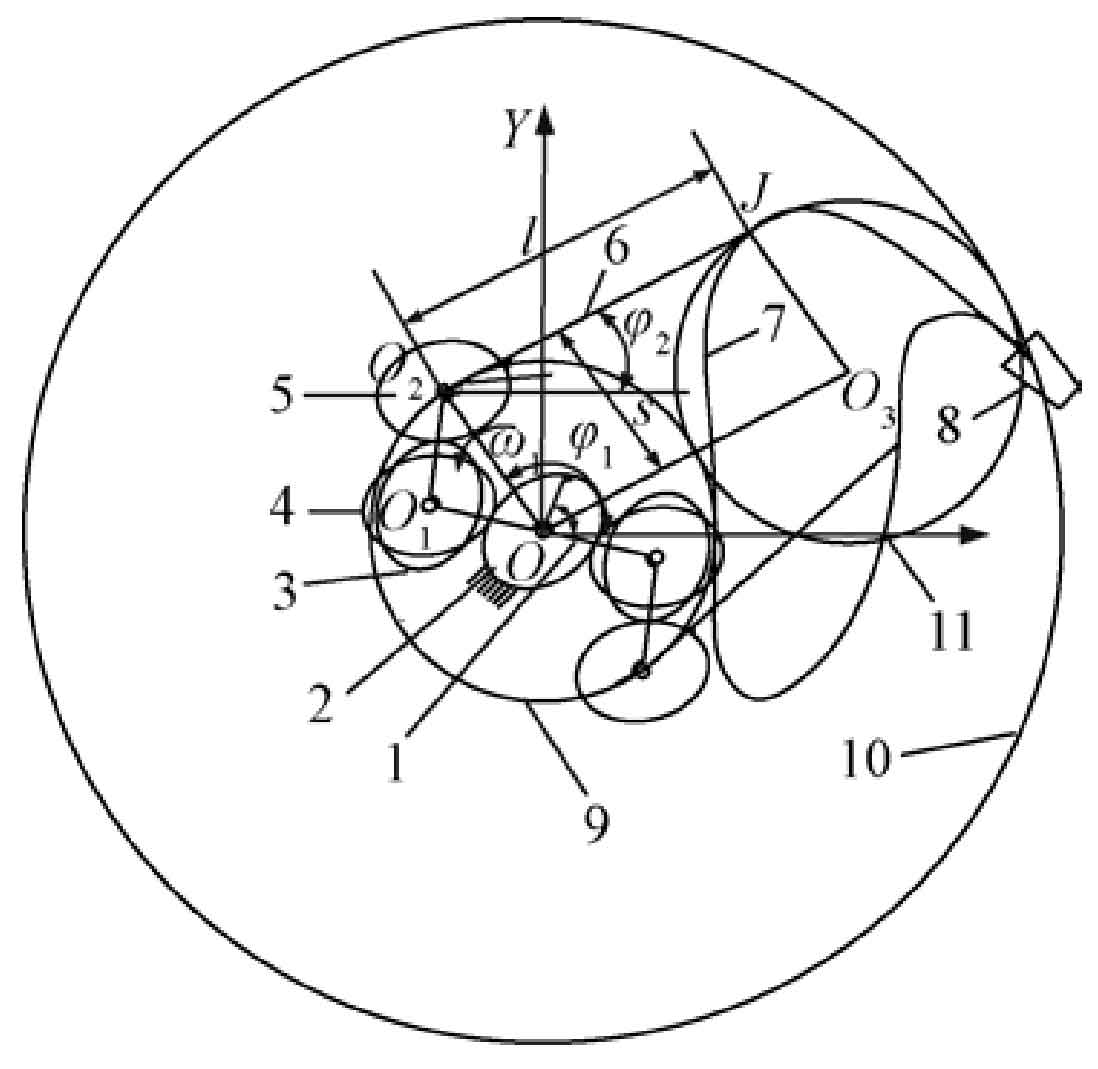
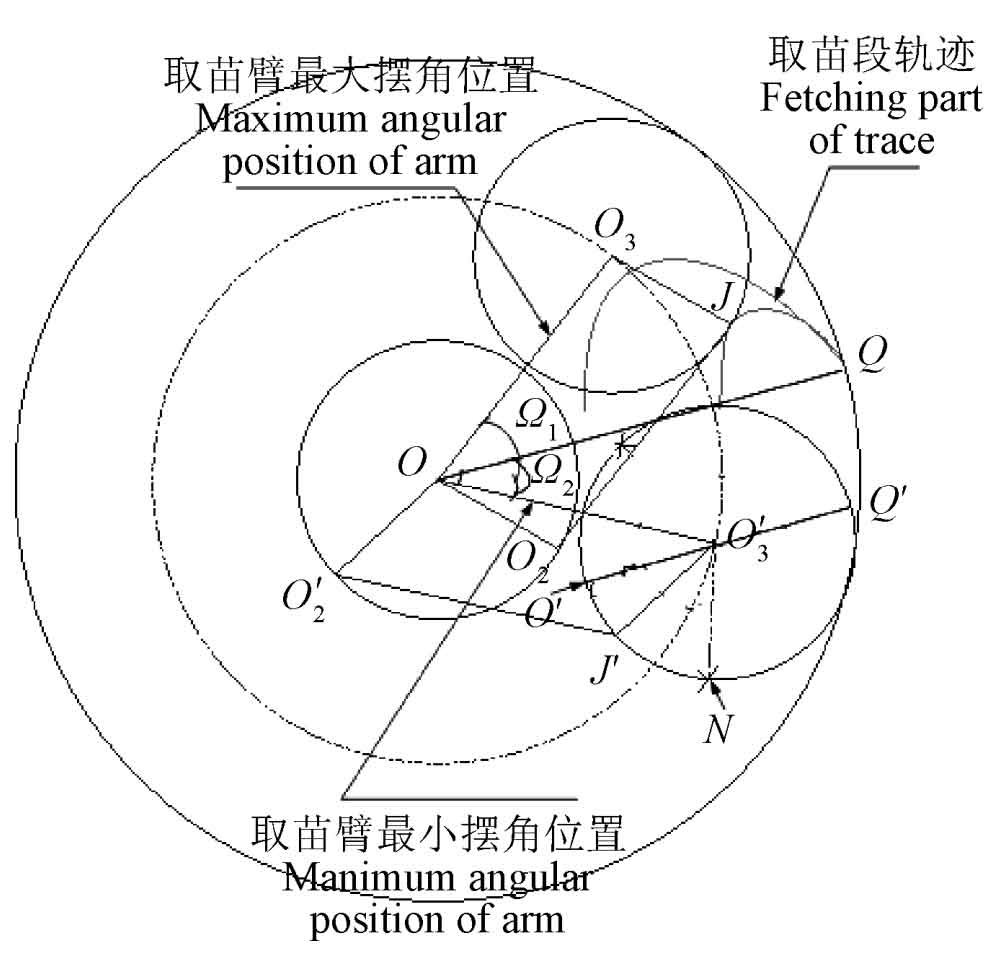
Figure 1 is the trajectory analysis diagram of planetary gear train mechanism. In order to illustrate the planning method of mechanism trajectory, a parallelogram o2ojo3 (shown in Fig. 1a) is constructed based on o2oj in Fig. 2. The trajectory of point J is O2J. With the synthesis of the involved trajectory of planet carrier oo2 and the relative trajectory of O2J and oo2, its trajectory is located in the ring determined by circle 9 and circle 10. Assuming that 25 I is constant 1, the angle of seedling arm O2J relative to the frame remains unchanged, and ∠ oo2j changes 360 ° in one motion cycle, Through the parallelogram o2ojo (3j), the point can be regarded as moving at constant speed on the circle 11 with O3 as the center and oo2 as the radius. When I25 is not constant, the virtual OO3 edge will swing with the same law as O2J. Similarly, the point J can be regarded as moving at non constant speed on the circle 11 with O3 as the center and oo2 as the radius.
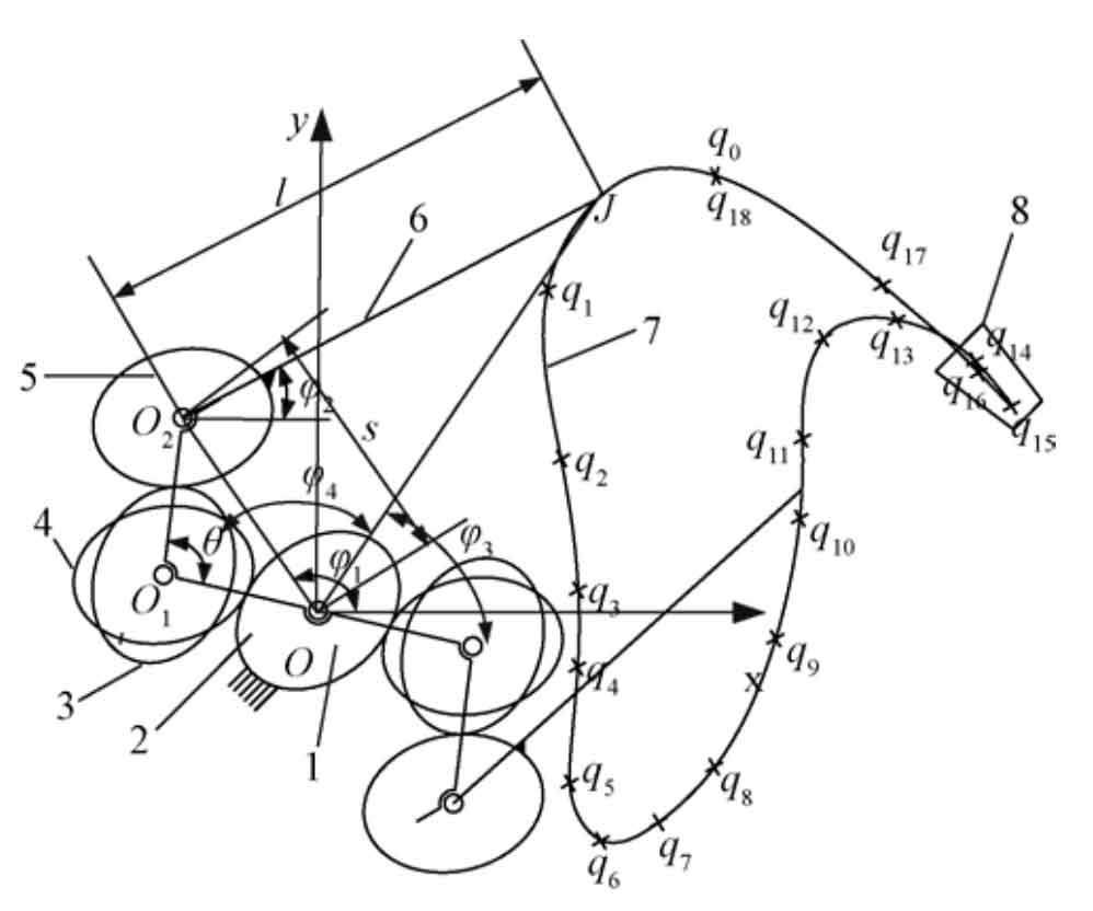
Note: qi(i=0,1,…,18) is data points; θ is angle of planet carrier, (°). s is length of planet carrier OO2, mm. l is length of picking-up seedling arm O2J, mm. J is endpoint of picking-up seedling arm. φ1 is angle between OO2 and x axis, (°). φ2is angle between picking-up seedling arm and x axis, (°). φ3 is angle between OJ and x axis, (°). φ4 is angle of triangle O2OJ, (°). Same as below.
Through the above transformation, when designing the expected trajectory of the mechanism, the swing angle range of the seedling arm O2J and the limit position of the trajectory can be planned through the work requirements, so that the trajectory is conducive to the realization of non-circular gear transmission and avoid excessive transmission ratio fluctuation. According to the requirements of seedling picking, the specific track planning steps are as follows:
Step 1: according to the requirements of seedling taking bowl, the circular area of mechanism track and seedling taking section track are predetermined. In the design, the cusp of the track is located on the outermost circle of the ring, which is conducive to the cooperation between the seedling taking mechanism and the seedling feeding device. Calculate the planet carrier length s and the seedling taking arm length L according to the size of the ring area.
Step 2: determine the maximum swing angle position OO3 of the seedling taking arm from the trajectory of the seedling taking section. When O2 is on a circle with o as the center and s as the radius, draw a graph to solve oo2 and O2J.
Step 3: determine the minimum swing angle of the seedling taking arm. At the sharp point of the seedling taking track, the seedling taking arm is in OQ. At this time, the seedling taking claw is parallel to the stem of the seedling. The seedling taking arm needs to transport the seedling to the vertical direction at the seedling feeding position. The minimum swing angle position OO ′ 3 of the seedling taking arm is determined by the seedling orientation in the seedling feeding device.
Step 4: determine the lowest position of the track. The minimum swing angle of the seedling taking mechanism at the lowest position of the trajectory should be maintained to facilitate seedling feeding. Since the J point of the seedling taking claw is on the circle with O ′ 3 as the center and oo2 as the radius, it is obtained that the lowest point of the seedling taking trajectory is located at point n in theory.
The seedling arm moves from the cusp of the track to the lowest position. When the J point is selected as o ‘, the rotation angle of the star carrier is exactly 180 °. At this time, the unequal amplitude transmission characteristics of the non-circular gear required in theory are small, which is conducive to the smooth transmission of the non-circular gear; In planning the lowest position of the seedling taking track, the cooperation with the seedling planting mechanism should also be considered to avoid the interference of the mechanism movement. Therefore, the J point of the seedling taking claw is selected on O ′ N and close to o ′ on the basis of meeting the cooperation of the mechanism.