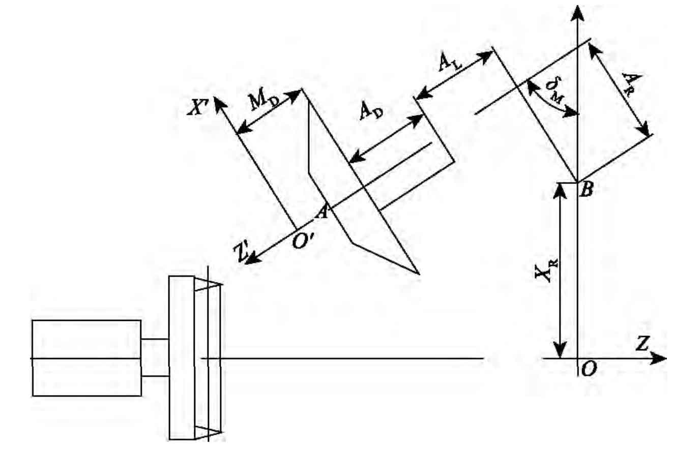
In order to measure the profile error of spiral bevel gear on machine, the spatial coordinates and normal vector parameters of discrete points on the theoretical tooth surface of spiral bevel gear in spiral bevel gear coordinate system need to be transformed into machine tool coordinate system. The relative position relationship between spiral bevel gear coordinate system and machine tool coordinate system is shown in the figure.
Let the spatial coordinates and normal vectors of each discrete point in the spiral bevel gear coordinate system SG = {o ‘; X’, y ‘, Z’} be (XG (I, J), YG (I, J), ZG (I, J)), (NX ‘(I, j), NY’ (I, J), NZ ‘(I, J)).
Let the spatial coordinates and normal vectors of each discrete point in the machine tool coordinate system SM = {o; X, y, Z} be (XM (I, J), YM (I, J), ZM (I, J)), (NX (I, J), NY (I, J), NZ (I, J)).
In order to convert the spatial coordinates and normal vector parameters of each discrete point from the coordinate system SG to the coordinate system SM, first change the directions of Y ‘axis and Z’ axis in the coordinate system SG, and then rotate the transformed coordinate system SG clockwise 90 ° – 90 ° around the Y ‘axis δ M. Let the spatial coordinates of each discrete point be (XG ‘(I, J), YG’ (I, J), ZG ‘(I, J)), and:
Then the spatial coordinates of each discrete point in the machine tool coordinate system are:
Where: AR and Al are machine tool constants, ad is the length of big wheel clamp, and MD is the installation distance of spiral bevel gear big wheel. Similarly, the normal vector parameters of discrete points on the theoretical tooth surface of spiral bevel gear can also be transformed into the machine tool coordinate system.


