1. Introduction
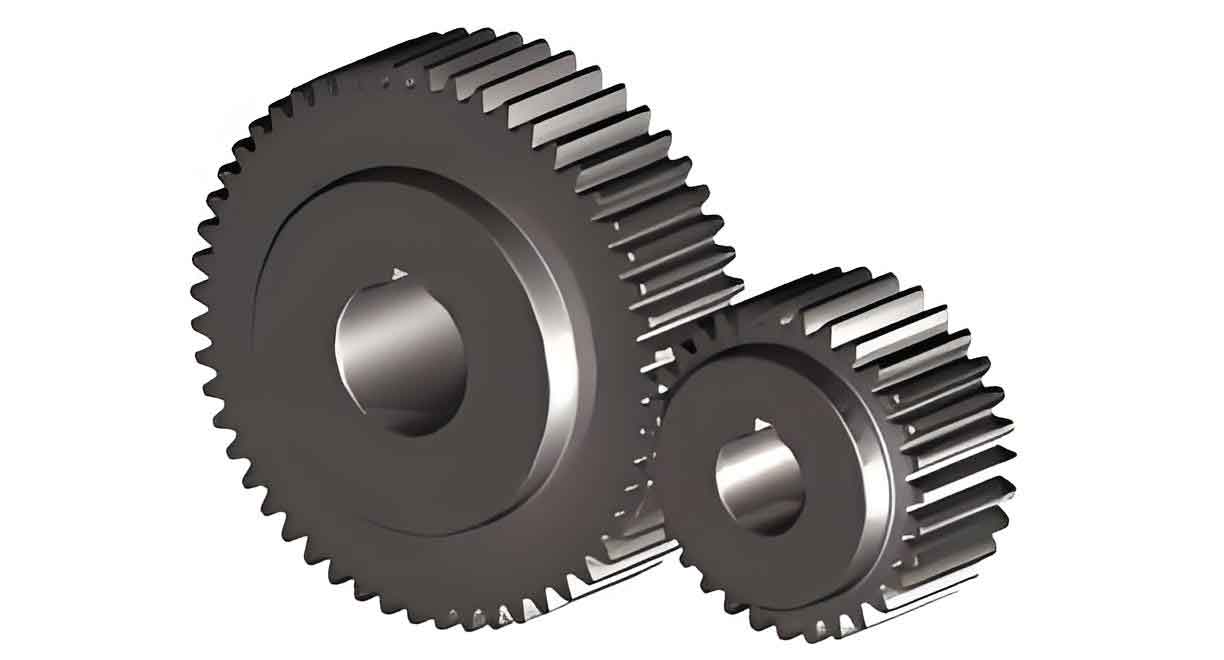
Spur gears are fundamental components in mechanical transmission systems, widely used in aerospace, wind turbines, and automotive industries. Their performance directly impacts the reliability and efficiency of mechanical systems. Among critical factors influencing spur gear dynamics, meshing stiffness and quasi-static transmission error (QSTE) stand out due to their direct correlation with vibration, noise, and fatigue life. However, tooth profile deviations caused by manufacturing tolerances (e.g., profile modification) and operational wear significantly alter these parameters, leading to dynamic instability and reduced lifespan.

Existing studies have focused on isolated effects of profile modification or wear, but the synergistic interaction between these deviations remains underexplored. This paper addresses this gap by proposing an improved analytical model that integrates structural coupling effects, angular contact, and time-varying wear. Our work aims to:
- Develop a high-precision meshing stiffness model for spur gears.
- Establish a quasi-static transmission error model accounting for profile deviations and wear.
- Quantify the impact of tooth profile errors and wear on gear dynamics.
2. Improved Analytical Model for Spur Gear Meshing
2.1 Meshing Stiffness Model with Structural Coupling Effects
Traditional meshing stiffness models consider Hertzian contact, bending, shear, axial compression, and fillet-foundation stiffness. However, structural coupling between adjacent gear pairs is often neglected. We extend the classical model by introducing extended fillet-foundation stiffness components.
The total meshing stiffness KtotalKtotal is expressed as:1Ktotal=1kh+∑i=1l(1kb,i+1ks,i+1ka,i+1kf,i)Ktotal1=kh1+i=1∑l(kb,i1+ks,i1+ka,i1+kf,i1)
where ll = number of simultaneously meshing tooth pairs.
For spur gears with a contact ratio < 2, adjacent tooth pairs interact structurally. The extended fillet-foundation stiffness kf12kf12 and kf21kf21 are derived using rotational displacement coordination principles:1kf12=cosα1cosα2EB[L∗(ufSf)2+tanα1(M∗+P∗ufSf)+⋯ ]kf121=EBcosα1cosα2[L∗(Sfuf)2+tanα1(M∗+P∗Sfuf)+⋯]1kf21=cosα1cosα2EB[L∗(ufSf)2+tanα2(M∗+P∗ufSf)+⋯ ]kf211=EBcosα1cosα2[L∗(Sfuf)2+tanα2(M∗+P∗Sfuf)+⋯]
Here, ufuf = deformation displacement, SfSf = geometric parameter, and L∗,M∗,P∗L∗,M∗,P∗ = empirical coefficients.
2.2 Quasi-Static Transmission Error Model
Tooth profile deviations create separation along the line of action, increasing QSTE. Wear further exacerbates this effect by altering contact geometry. Our QSTE model incorporates:
- Tooth profile modification
- Wear depth
- Angular contact effects
The QSTE ΔQSTEΔQSTE is formulated as:ΔQSTE=A1F1+A2pF1+E0+SaΔQSTE=A1F1+A2pF1+E0+Sa
where A=1KA=K1 (compliance), E0E0 = cumulative deviation from profile errors and wear, and SaSa = angular contact-induced separation.
For dual-tooth contact regions:ΔQSTE=Fm(A12−A2p)+Sa+(E02−E01)A11+A22−A2p1−A2p2ΔQSTE=A11+A22−A2p1−A2p2Fm(A12−A2p)+Sa+(E02−E01)
Unloaded separation SaSa is critical for determining actual contact conditions.
2.3 Time-Varying Wear Model
Wear depth δbδb is calculated using the Archard model:δb=∑i=1N2LiKmPma∣usli−us2i∣(1usli+1us2i)δb=i=1∑N2LiKmPma∣usli−us2i∣(usli1+us2i1)
where KmKm = wear coefficient, PmPm = contact pressure, and usus = sliding velocity.
3. Model Validation and Case Studies
3.1 Model Validation
The analytical model was validated against finite element analysis (FEA) for two spur gear pairs (Table 1).
Table 1: Gear Pair Parameters
| Parameter | Gear Pair 1 | Gear Pair 2 |
|---|---|---|
| Teeth (z1/z2z1/z2) | 30/30 | 20/30 |
| Module (mm) | 2 | 4 |
| Pressure Angle (°) | 20 | 20 |
| Face Width (mm) | 20 | 40 |
3.2 Impact of Tooth Profile Modification
How profile modification (CcCc) and length (LL) affect meshing stiffness. Key findings:
- Higher CcCc shifts contact points, delaying single-tooth engagement.
- LL has minimal impact compared to CcCc.
Table 2: Meshing Stiffness Under Profile Modification
| CcCc | Stiffness (Worn) [N/m] | Stiffness (Unworn) [N/m] | Change Rate |
|---|---|---|---|
| 0.2 | 2.16E+08 | 2.13E+08 | 0.0126 |
| 0.4 | 2.10E+08 | 1.90E+08 | 0.1017 |
| 0.6 | 1.99E+08 | 1.85E+08 | 0.0759 |
3.3 Impact of Wear
Wear progressively dominates gear dynamics. After 100,000 cycles:
- Meshing stiffness reduction rate drops from -0.1963 to -0.0196.
- Profile modification effects diminish due to wear depth accumulation.
Table 3: Meshing Stiffness Under Wear
| Cycles (n) | Stiffness (Worn) [N/m] | Stiffness (Unworn) [N/m] | Change Rate |
|---|---|---|---|
| 10,000 | 1.85E+08 | 2.31E+08 | -0.1963 |
| 100,000 | 2.13E+08 | 2.18E+08 | -0.0196 |
3.4 Quasi-Static Transmission Error Analysis
QSTE increases with both profile modification and wear. Wear amplifies deviations, especially at high CcCc values.
Table 4: QSTE Under Profile Modification
| CcCc | QSTE (Worn) [µm] | QSTE (Unworn) [µm] | Change Rate |
|---|---|---|---|
| 0.2 | 30.9 | 25.0 | 0.2383 |
| 0.8 | 39.9 | 28.7 | 0.3926 |
4. Conclusions
- Improved Meshing Stiffness Model: Our model integrates structural coupling and angular contact effects, achieving >95% accuracy compared to FEA with 60% faster computation.
- QSTE Dynamics: Tooth profile errors and wear significantly alter QSTE distribution. Wear becomes dominant over time, reducing the influence of initial profile modifications.
- Design Implications: Engineers must prioritize wear-resistant materials and lubrication for long-term spur gear reliability.
