
The transmission between the eccentric gears will produce the change of backlash. Therefore, when calculating the coefficient of deflection of the eccentric gears in the transmission of the eccentric gears and the eccentric gears, we must first understand the law of the change of backlash of the eccentric gears. In the study of the trajectory of the claw tip of the planetary system transplanting mechanism with eccentric displacement and eccentric gear drive, the eccentric gear drive is used to replace the eccentric and eccentric gear drive planetary system transplanting mechanism, which will simplify the analysis process and also meet the requirements of the trajectory and angular displacement accuracy of the claw.
Two identical eccentric gears I and II are engaged, as shown in Figure 1. In the initial position, the angle between the axis OB and X axis is φ 0, oo1 and ob coincide, and Bo2 is on the OB extension line. When gear I turns φ 1 and gear II turns φ 2, O1O2 and ob intersect at point a.
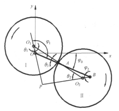
According to the transmission property of eccentric gear [3], the geometric center distance of any position of gears I and II is
lΟ1Ο2=lAΟ1+lAΟ2=a (|sinφ1|+|sinφ2|) 2|sinθ1| (1)
Where a – axis distance of two gears
It can be seen from formula (1) that in the process of eccentric gear pair transmission, the geometric center distance of two gears changes with the angular displacement of the gear, so the backlash of the gear side also changes.
At any time, the eccentric gear transmission can be regarded as the meshing of two standard cylindrical gears with a center distance of lo1o2, and its rotation centers are O1 and O2 respectively, but the center distance of the two gears is no longer the standard center distance all the time, and there is a side gap between the meshing tooth surfaces of the two eccentric gears. The angular displacement of the gear is divided into N parts within the range of 0 ° – 360 °. At each point of the pitch curve of the corresponding gear, the angle of the gear is shifted, so as to change the tooth thickness of the gear and make the backlash of the gear side zero.
According to the relationship between center distance and pressure angle [9], the actual pressure angle can be calculated
α=arccosa0cosα0lΟ1Ο2) (2)
Where A0 — standard center distance, A0 = 2R
α 0 – standard gear pressure angle
Suppose the backlash between the two eccentric gears is C, in order to compensate the backlash, the eccentric gears are modified, and the transmission of the eccentric modified gears meets the meshing condition without backlash. The meshing equation of toothless side clearance is [10]
invα=2 (x1+x2) tanα0z1+z2+invα0 (3)
Where inv α = Tan α – α inv α 0 = Tan α 0 – α 0
In the formula, Z1, Z2 — number of teeth of gear I and II, and Z1 = Z2 = Z
X1, X2 — modification coefficient of gears I and II
Since the eccentric gear is easy to be machined, the eccentric gear I is kept unchanged, and only the eccentric gear II is displaced, that is
X1=0 x2=x
The modification coefficient of gear II is obtained as
x=z (invα-invα0) /tanα0 (4)
So the backlash of eccentric gear is
C=2mxtanα (5)
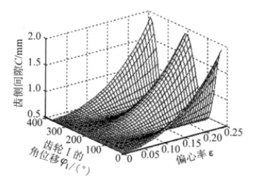
Fig. 2 shows the relationship between the backlash C between teeth and the angular displacement φ 1 and eccentricity ε. It can be seen from the figure that the backlash changes periodically within one week of gear rotation. With the increase of eccentricity, the backlash increases, which is far beyond the allowable range. If this kind of gear is applied to the transplanting mechanism of rice transplanter, the tooth side clearance will be transmitted to the rice seedling needle through the gear and the planting arm, causing the vibration of the transplanting mechanism and the swing of the rice seedling needle. If it is light, the amount of rice seedling will be uneven, and if it is heavy, the rice seedling needle will not reach the rice seedling or collide with the rice seedling gate.
In order to avoid too large coefficient of displacement and reduce the degree of coincidence, and in order to reduce the size of the structure, under the premise of meeting the strength of the gear without undercutting, reduce the axis distance properly. The axial distance between eccentric gear and eccentric displacement gear is [11]
A=dR (6)
Where d = 2 + ε 22 + 35 ε 432
Where D — relative center distance of two gears
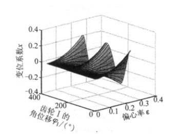
Fig. 3 shows the relationship between the modification coefficient X and the angular displacement φ 1 and the eccentricity ε. It can be seen from the figure that the modification coefficient is positive and negative. If the eccentricity is zero, the modification coefficient is zero, no modification is needed. If the eccentricity is not zero, the modification coefficient changes periodically. The gear rotates twice a week, and the larger the eccentricity is, the greater the fluctuation is, and the fluctuation law is the same. At 0 ° and close to 180 ° the coefficient of deflection is the largest, and at slightly less than 90 ° and slightly more than 270 ° the coefficient of deflection is the smallest.