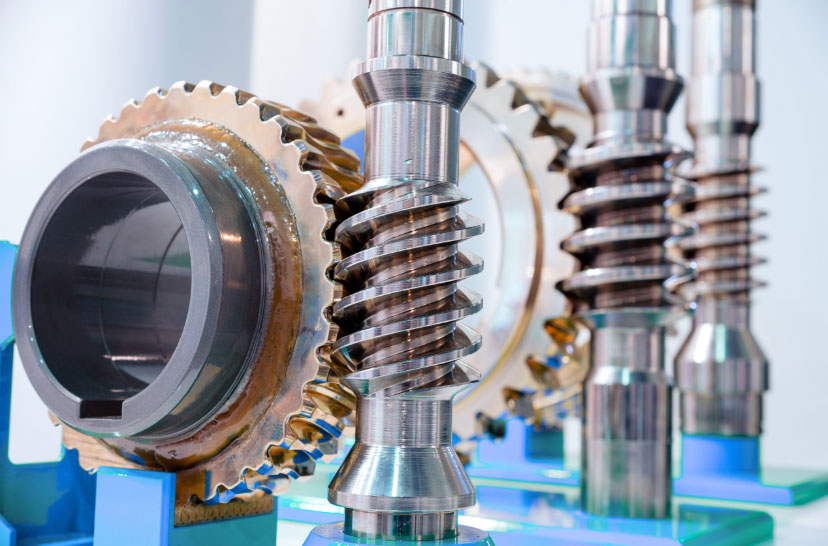
Designing and manufacturing helical gears involves several important considerations to ensure their precision and functionality. Let’s explore the key aspects of designing and manufacturing helical gears:
Design Considerations:
- Helix Angle: The helix angle is a critical design parameter for helical gears. It determines the angle at which the gear teeth are twisted relative to the gear axis. The helix angle affects the gear’s load-carrying capacity, efficiency, and smoothness of operation. The angle should be chosen carefully based on the specific application requirements.
- Module or Diametral Pitch: The module (for metric systems) or diametral pitch (for the imperial system) determines the size and spacing of the gear teeth. It is crucial to select an appropriate module or diametral pitch to achieve the desired gear ratio and ensure proper meshing with other gears in the system.
- Number of Teeth and Gear Ratio: The number of teeth on a helical gear impacts its performance and engagement characteristics. Choosing suitable gear ratios and tooth counts is essential for achieving the desired speed and torque transmission.
- Pressure Angle: The pressure angle is the angle between the line of action and the tangent to the pitch circle. Common pressure angles for helical gears are 14.5°, 20°, and 25°. The pressure angle influences the gear’s strength and load distribution.
- Center Distance and Shaft Alignment: Proper alignment of the gears’ shafts and correct center distance between the gears ensure smooth and efficient power transmission while minimizing wear and noise.
- Backlash: Backlash is the play between meshing teeth in a gear pair. Minimizing backlash is crucial for precision motion control applications and to avoid issues like positioning errors and vibration.
- Material Selection: The choice of gear material depends on factors like load, operating conditions, and manufacturing considerations. Common materials for helical gears include steel, cast iron, bronze, and various alloys.
Manufacturing Methods:
- Gear Cutting Techniques: Helical gears can be manufactured using various techniques, including hobbing, shaping, milling, and broaching. Hobbing is one of the most common methods for producing helical gears, where a special cutting tool (hob) generates the helical tooth profile.
- Quality Control: Precision in manufacturing is crucial for helical gears. Quality control measures such as gear inspection using specialized machines, coordinate measuring machines (CMM), and gear analyzers ensure the gears meet the required specifications.
- Heat Treatment: After the gears are cut, they usually undergo heat treatment processes such as carburizing or quenching to improve their hardness and durability.
- Surface Finishing: Grinding or lapping may be performed to achieve a smooth surface finish and improve the gear’s performance.
- Lubrication and Noise Reduction: Proper lubrication and noise reduction techniques, such as the use of profile modifications, help ensure smooth operation and reduced noise levels in helical gears.
- Post-Processing: Gears may undergo additional processes like deburring, coating, or finishing to meet specific application requirements.
The design and manufacturing of helical gears require precision engineering and attention to detail. Proper design considerations, accurate manufacturing techniques, and quality control measures play crucial roles in ensuring the functionality, efficiency, and durability of helical gears.
