
In UG software, the CAM module covers a variety of processing methods, such as CNC milling, CNC turning, wire cutting and electric discharge machining. Different processing methods generate corresponding NC programs and tool path paths, of which CNC milling is the most widely used. In terms of milling processing methods, there are mill plane, mill cavity, fixed axis surface contour milling Contour variable profile milling, etc.
Import the established 3D model of double circular arc helical gear into the application module of UG software, select “machining” to enter the processing environment, select multi-axis milling in the CAM session, and create a ball-end milling cutter. To ensure no over-cutting, the diameter of the cutter head should be smaller than the diameter of the end face tooth profile arc, because the ball head diameter of the ball-end milling cutter selected for this processing is set as φ 1 mm, cone angle is 0, length is 50 mm, blade length is 6 mm, ball end milling cutter is of integral structure.
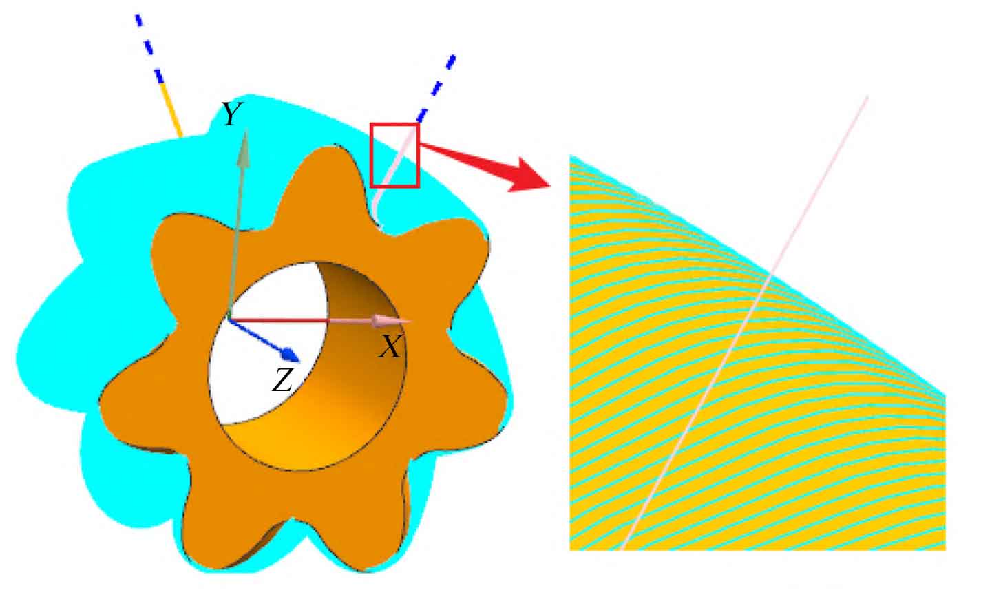
In the machining environment, select the “ball-end milling cutter” created by the tool type, specify the part as the “double-arc spiral gear model”, specify the blank as the “containing cylinder”, the radius offset is 0.2 mm, select the “surface area” for the drive method, select the “cutter axis” for the vector, and select the “away from the straight line” for the cutter axis. Because the removal allowance is small, set the rough machining allowance to 0.03 mm, and set the machining allowance to 0 when finishing, Given an appropriate feed rate, set the spindle speed of the machine tool to 1200 r/min, click Generate below to generate the tool path path for machining, and generate the tool path path for finishing machining, as shown in Figure 1.
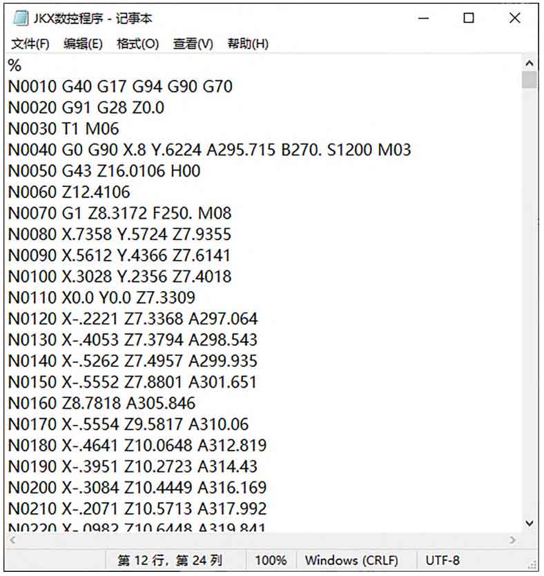
UG provides a good visual operation of the machining process. After determining the tool path path, the animation demonstration of the simulation process can be carried out. This method also carries out modeling and numerical control processing in the software to ensure the accuracy of the program. Finally, select the post-processor and program output position in the process navigator. Some NC programs are shown in Figure 2.