The tooth profile of the involute double-circular-arc helical gear is related to the module, tooth number, pressure angle and tooth width. In combination with the basic relationship of the double-circular-arc helical gear, the basic parameters of the double-circular-arc helical gear are given as shown in Table.
| Name | Driving wheel | Driven wheel |
| Normal modulus mn/mm | 2 | 2 |
| End face modulus mt/mm | 2.57 | 2.57 |
| Number of teeth z/piece | 7 | 7 |
| Pressure angle an (/°) | 28 | 28 |
| Tooth width B/mm | 10 | 10 |
| Helix angle β (/ °) | 39 | 39 |
Limited by the ability of UG and other software to draw curves, the involute transition curve between two adjacent gears is generated in MATLAB, and the points in the involute are output in. dat format file. Based on the basic parameters of double-arc helical gears in Table, the involute generation program and coordinate output program are compiled.
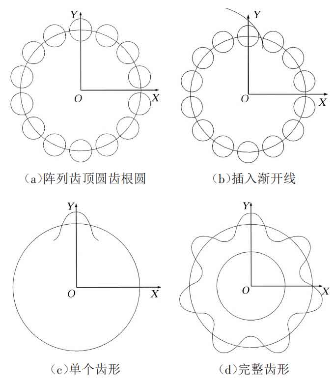
In UG, the basic parameters of double-arc helical gear, such as tooth number, module, pressure angle, are defined by creating expressions, and the parameters such as tooth tip circle diameter and base circle diameter are calculated by expressions. The geometric dimension position of double-arc helical gear can be accurately drawn by using UG expressions. The center of the upper and lower arc circles fall on the dividing circle with O as the center, and the radius of the dividing circle and the upper and lower arc are R and r respectively. The formation process of the tooth profile of the end face of the double-arc helical gear is shown in Figure 1.

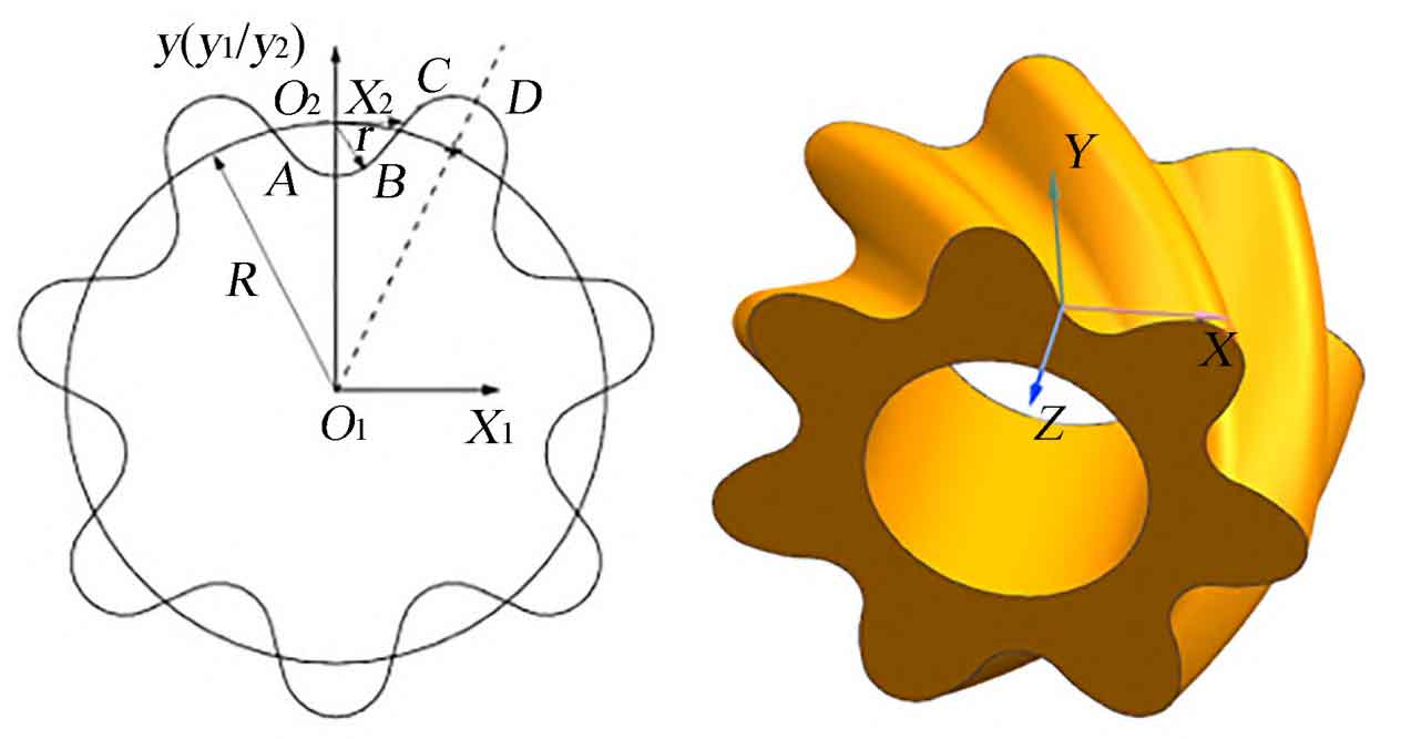
The single tooth profile of involute double-arc helical gear is smoothly connected by the upper and lower arc CD and AB by the involute BC. The involute is imported in UG in the way of “through point”. The drawing of the tooth profile of the involute gear end face can be realized by using the commands of trimming, mirroring, array, etc. The 3D model is built by using the spiral sweep in the 3D modeling software UG12.0: select “menu – insert – curve – helix” in turn, Specify the coordinate system in the orientation and set the helix angle. Select Diameter in the Size option. The rule type is set to a constant value of 18 mm. The pitch type is constant. The value is determined by the formula. The calculation result is about 70 mm.

Where, L is the pitch, mm; D is the diameter of the graduation circle, mm; β Is the helix angle, (°).

Set the helix length option to “Limit”, set the start limit to 0, and the end limit to 10 mm. Click OK to generate the helix, and use the same method to generate 3 helices on the indexing circle; Then select “Menu – Insert – Sweep – Sweep (create a body by sweeping the section with the guide line)”, select the end tooth profile of the gear, select the three helical lines made by the guide line in turn, and click OK to generate the 3D model of the double-arc helical gear. Similarly, change the helix angle to a negative value, and the driven gear in the rotor system of the double-circular-arc helical gear pump can be established according to the above method. The tooth profile and three-dimensional model of the end face of the double-circular-arc helical gear are shown in Figure 2.
