
The harmonic drive gear, also known as a strain wave gear, represents a paradigm shift in precision motion control. Its unique operating principle, leveraging controlled elastic deformation, enables exceptional performance characteristics unattainable with conventional geared systems. In this comprehensive exploration, I will delve into the fundamental working principles, detailed kinematics, unique mechanical advantages, and practical design considerations of the harmonic drive gear, underscoring its pivotal role in modern, compact, and high-performance machinery.
The core principle of the harmonic drive gear is elegantly simple yet mechanically profound. It operates on the concept of a moving elastic wave, hence the name “harmonic.” The system comprises three primary components:
- The Wave Generator (WG): This is the input component, typically consisting of an elliptical cam (or a multi-lobed cam for higher wave counts) surrounded by a special thin-race ball bearing. As the cam rotates, it imparts a controlled, repeating elliptical deformation to the bearing’s outer race.
- The Flexspline (FS): This is a thin-walled, flexible cylindrical cup with external teeth machined near its open end. It is made from high-strength, high-endurance alloy steel to withstand continuous elastic deformation.
- The Circular Spline (CS): This is a rigid, non-deforming ring with internal teeth. It has a slightly different number of teeth than the Flexspline, usually two teeth more for a standard dual-wave configuration.
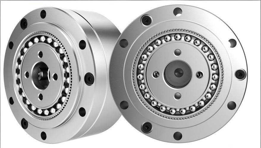
The assembly process involves inserting the wave generator into the flexspline, causing the flexspline to assume an elliptical shape. This elliptical flexspline is then partially meshed with the circular spline. The fundamental kinematic relationship arises from the difference in tooth counts. If the circular spline has \(N_c\) teeth and the flexspline has \(N_f\) teeth, the tooth difference is given by:
$$ \Delta N = N_c – N_f $$
For a standard dual-wave harmonic drive gear, \(\Delta N = 2\).
Kinematic Analysis and Gear Ratio
The motion transfer is based on the phenomenon of “tooth differential” or “strain wave” motion. When the wave generator rotates, it propagates the elliptical deformation wave around the flexspline. At the major axis of the ellipse, the flexspline teeth are in full engagement with the circular spline teeth. At the minor axis, they are completely disengaged. The zones between represent transition phases of meshing-in and meshing-out.
Since the circular spline has more teeth, each complete revolution of the wave generator causes the flexspline to retrograde by a number of teeth equal to the difference \(\Delta N\). Therefore, for one clockwise revolution of the wave generator, the flexspline moves counterclockwise relative to the circular spline by \(\Delta N\) teeth. The absolute rotational displacement of the flexspline is:
$$ \theta_f = – \left( \frac{\Delta N}{N_f} \right) \times 360^\circ $$
for one revolution of the wave generator.
This leads to the fundamental speed reduction formula. The gear ratio depends on which component is fixed and which is the output. The two most common configurations are:
| Fixed Component | Input Component | Output Component | Gear Ratio (i) | Output Direction |
|---|---|---|---|---|
| Circular Spline (CS) | Wave Generator (WG) | Flexspline (FS) | $$ i = -\frac{N_f}{\Delta N} $$ | Opposite to input |
| Flexspline (FS) | Wave Generator (WG) | Circular Spline (CS) | $$ i = +\frac{N_c}{\Delta N} $$ | Same as input |
Given that \(\Delta N\) is small (typically 2), the magnitude of the gear ratio is very high, approximately equal to \(N_f / 2\) or \(N_c / 2\). For example, with a flexspline of 200 teeth and a circular spline of 202 teeth:
$$ i_{CS-fixed} = -\frac{200}{2} = -100:1 $$
$$ i_{FS-fixed} = +\frac{202}{2} = +101:1 $$
This demonstrates the harmonic drive gear’s ability to achieve high reduction ratios in a single, compact stage—a feat requiring multiple stages in traditional planetary or spur gear systems.
Unique Meshing Characteristics and Advantages
The harmonic drive gear’s performance stems from its unique multi-tooth meshing. Unlike conventional gears with 1-2 tooth pairs in contact, a significant percentage (often 10-30%) of the teeth in a harmonic drive gear are simultaneously engaged along the major axis of the ellipse. This multi-tooth contact distributes the load across many teeth, leading to exceptional advantages:
| Characteristic | Mechanism in Harmonic Drive Gear | Resulting Advantage |
|---|---|---|
| High Torque Capacity | Load distributed over 15-30% of total teeth. | High torque-to-weight and torque-to-volume ratios. |
| Zero Backlash & High Precision | Pre-loaded tooth engagement due to elastic deformation; no clearance between mating teeth. | Excellent positional accuracy, repeatability, and torsional stiffness. Crucial for robotics and aerospace. |
| High Single-Stage Ratio | Gear ratio derived from tooth difference (\(\Delta N\)), not absolute tooth counts. | Ratios from 30:1 to over 300:1 in a compact, coaxial package. |
| Coaxial Input/Output | Inherent design of nested components (WG inside FS inside CS). | Simplifies mechanical design, saves space, and allows for hollow shaft configurations. |
However, the sliding contact inherent in the elliptically-deforming mesh, as opposed to pure rolling, introduces a unique consideration. The relative motion between the tooth flanks involves a combination of rolling and sliding, which can affect efficiency and requires specific lubrication strategies. The sliding velocity \(v_s\) at the tooth contact can be approximated by:
$$ v_s \approx \frac{\pi d_m (\omega_{wg} – \omega_{fs})}{2} \cdot \sin(2\phi) $$
where \(d_m\) is the mean pitch diameter, \(\omega\) are angular velocities, and \(\phi\) is related to the pressure angle. This kinematic action, while contributing to some power loss, is fundamental to the self-centering and anti-backlash properties of the harmonic drive gear.
Wave Generator Configurations and Design Variations
The heart of the system is the wave generator. Its design directly influences performance, stiffness, and service life. Common types include:
| Type | Description | Pros | Cons |
|---|---|---|---|
| Elliptical Cam + Ball Bearing | Classic design: elliptical cam spins inside a specially designed “cam follower” bearing. | Robust, predictable performance, high torque capacity. | Bearing life can be a limiting factor; requires precision manufacturing. |
| “Pancake” or Disk Wave Generator | Uses a set of rolling elements (balls or rollers) guided by a wave-generating disk. | Lower bearing stress, potentially higher life, compact axial profile. | More complex assembly. |
| Planetary Roller Type | Uses freely rotating rollers positioned by a planetary mechanism to create the wave. | Very high stiffness, excellent for ultra-precision and high-load applications. | Most complex and costly design. |
| Electromagnetic Wave Generator | Uses controlled electromagnetic forces to deform the flexspline directly. | No mechanical contact, theoretically infinite resolution, zero wear. | Limited torque, complex control, still largely in research. |
The choice of wave generator directly impacts the stress state in the flexspline, which is the life-limiting component. The flexspline undergoes cyclic bending stress with each revolution of the wave generator. Proper material selection (e.g., high-cycle fatigue strength alloys like 35NCD16), heat treatment, and precise tooth geometry are paramount for reliability.
Application Advantages and Component Selection
The specific advantages of the harmonic drive gear make it indispensable in numerous fields. A key design flexibility is the choice of fixed and output components to achieve specific layout goals.
Application 1: Compact, Coaxial Actuator with Central Output. A common challenge in robotics and automation is designing an actuator where the output member (e.g., a drive flange) is located between the motor and the reducer body. Using a harmonic drive gear with the flexspline fixed and the circular spline as the output elegantly solves this. The motor connects to the wave generator. The flexspline is anchored to the housing. The circular spline, which now rotates, forms the central output flange. This configuration, governed by the ratio \(i = +N_c / \Delta N\), provides a compact, in-line design where the output is “sandwiched” between the motor and the fixed housing, optimizing space utilization in joint designs.
Application 2: High-Precision Rotary Table with Hollow Shaft. For applications requiring a hollow shaft for wiring, piping, or optical pathways, fixing the circular spline and using the flexspline as the output is ideal. The flexspline, being a thin-walled cup, naturally provides a large through-hole. The motor-driven wave generator rotates inside, and the flexspline outputs the reduced motion. This is critical in semiconductor manufacturing equipment and advanced machine tools.
The decision matrix for selecting the fixed component is summarized below:
| Design Goal / Constraint | Recommended Configuration | Rationale |
|---|---|---|
| Maximum Hollow Shaft Diameter | Fix Circular Spline, Output from Flexspline. | Flexspline cup provides the central hollow bore. |
| Output Flange at Actuator’s Mid-Section | Fix Flexspline, Output from Circular Spline. | Circular spline can be designed as a central output flange. |
| Slightly Higher Gear Ratio (Magnitude) | Fix Flexspline, Output from Circular Spline. | Ratio \(N_c/\Delta N\) is slightly larger than \(N_f/\Delta N\). |
| Simplified Housing (Anchoring a rigid ring) | Fix Circular Spline. | Easier to rigidly mount the external circular spline. |
| Integration of Brakes/Sensors in Bore | Fix Flexspline. | The stationary flexspline bore offers a cavity to house auxiliary devices. |
Design Considerations and Future Perspectives
Implementing a harmonic drive gear requires careful attention beyond ratio calculation. Key considerations include:
- Torsional Stiffness: While high, it is finite and non-linear near zero torque due to the pre-loaded mesh. The stiffness curve \(K(\tau)\) is crucial for servo control stability in robotics.
- Efficiency: Ranges from 60% to 90% depending on size, ratio, speed, and load. Losses come from sliding friction in the tooth mesh and wave generator bearing friction. Efficiency \(\eta\) can be modeled as:
$$ \eta \approx 1 – \left( \frac{P_{sliding} + P_{bearing}}{P_{in}} \right) $$ - Temperature and Lubrication: Proper lubrication is critical for wear protection and heat dissipation. Grease is common, but oil lubrication or even solid lubricants are used in extreme environments (vacuum, cryogenics).
- Error Motions: Despite zero backlash, harmonic drive gears exhibit small periodic errors (like “cogging”) due to tooth mesh harmonics and manufacturing tolerances, which must be characterized for ultra-precision systems.
Future developments in harmonic drive gear technology focus on advanced materials like carbon-fiber-reinforced composites for the flexspline to reduce inertia, improved bearing designs for longer life, and integrated mechatronic designs combining the motor, harmonic drive gear, sensors, and controller into a single “smart actuator” module. The fundamental principle of the harmonic drive gear—using controlled elasticity to achieve superior mechanical performance—ensures its continued dominance in applications demanding the ultimate in compactness, precision, and reliability, from the joints of Mars rovers to the precision stages in lithography machines. Its unique blend of high ratio, zero backlash, and coaxial design remains unmatched by any other power transmission technology.