
Based on Mathematica software, draw the right tooth surface of one tooth of spur cylindrical gear, and combine the right tooth surface models of two spur cylindrical gear teeth obtained by simulation, as shown in Figure 1.
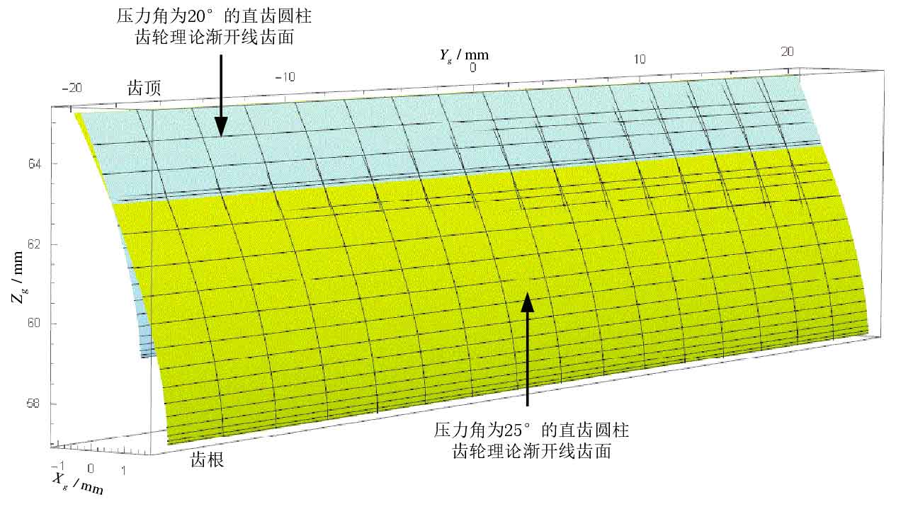
In Figure 1, the light cyan involute tooth surface is the theoretical involute tooth surface of spur cylindrical gear with pressure angle of 20 °, and the Yellow involute tooth surface is the theoretical involute tooth surface of spur cylindrical gear with pressure angle of 25 °. It can be seen from Figure 1 that the number of teeth and modulus of the gear are the same, and the larger the pressure angle at the indexing circle, the smaller the radius of the base circle, which is consistent with the formula of the radius of the base circle.
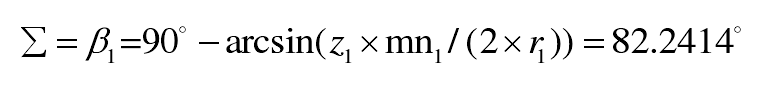
According to the basic parameters of spur gear hob and gear in table 4-1, the installation error E Σ of shaft intersection angle Σ and the helix angle of spur gear are not considered β 2 = 0, according to the formula, the axial intersection angle Σ between the straight cylindrical gear hob axis and the gear axis is obtained:
The installation center distance is not considered α Installation error e α 。 From the formula, the center distance:
The point C at the indexing circle of the gear tooth surface in the gear coordinate system SG is transformed into the straight cylindrical gear hob coordinate system SW through the spatial coordinate transformation matrix, and the spatial coordinate value at the node P meshed between the involute helical surface of the straight cylindrical gear hob and the gear tooth surface is obtained. Then, the equations are established through the involute helical surface of the straight cylindrical gear hob and the spatial coordinate value at the node P, It can be solved that ZP = 4.9618333mm.
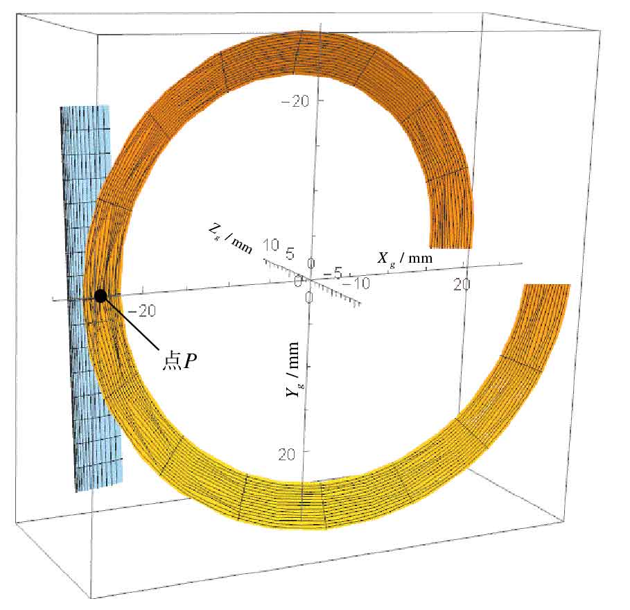
The three-dimensional simulation model of spur gear hob and gear meshing is shown in Figure 2. Point P is the meshing point between spur gear hob and gear.
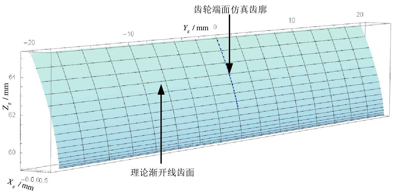
Through the digital simulation of spur gear hobbing process, the simulated tooth profile of gear end face with pressure angle of 20 ° is obtained. The simulated gear is combined with the theoretical involute tooth surface, as shown in Figure 3.