In the process of cutting teeth, the material of straight bevel gear blank continues to be cut off, and the overall stiffness of straight bevel gear blank will gradually decrease in theory. However, considering that the stiffness reduction degree caused by different cutting positions of the split gear blank in machining is different, the change of the stiffness of the straight bevel gear blank is not only an influencing factor of the amount of material removal, but also the position of the cutting teeth may have a significant impact on the stiffness of the straight bevel gear blank. The bending strain energy equivalent stiffness calculation method introduced before just includes these two influencing factors, so this method is reliable for the prediction of stiffness in the processing of straight bevel gear blank.
In order to explore the variation law of stiffness in the machining process of straight bevel gear blank, according to the above equivalent calculation principle, it is necessary to establish the model of straight bevel gear blank for analysis first. The module of the straight bevel gear selected in the paper is m = 20, the number of teeth is Z = 60, the split cone angle is 89 °, and the tooth height is 2.25m = 45mm. The whole ring straight bevel gear blank is divided into ten parts, one of which is taken as the straight bevel gear blank. The straight bevel gear blank is the research model of the paper. The dimension of the split wheel blank of straight bevel gear is measured, and its length, width and height are 340mm, 100mm and 80mm respectively.

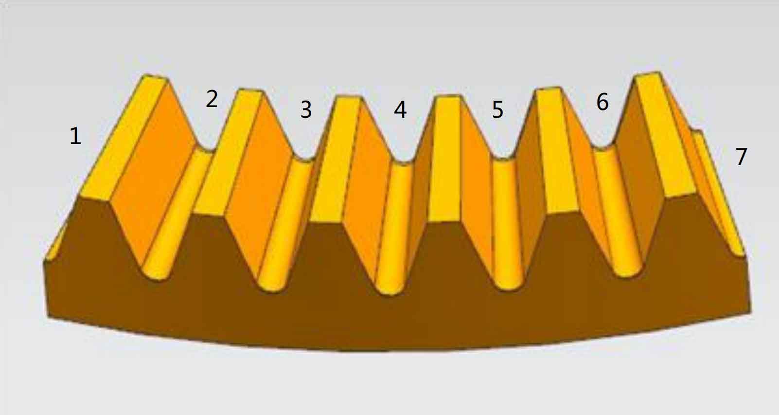
The tooth surface points generated by MATLAB program are imported into UG, and the established model is shown in Figure 1. The straight bevel gear blank needs to cut a total of 5 slots and two half slots at the left and right ends. According to the structural characteristics and processing technology of the straight bevel gear split wheel blank, there are two possible cutting processing sequences: one is to process each tooth groove from the left end to the right end of the straight bevel gear blank, the other is to process the middle tooth groove of the straight bevel gear blank, then process the right half of the wheel blank to the right, and then process the tooth groove of the left half of the wheel blank from the middle to the left. If the complete removal of the material in any tooth groove is a work step, there are 14 material removal states in the process of tooth cutting.

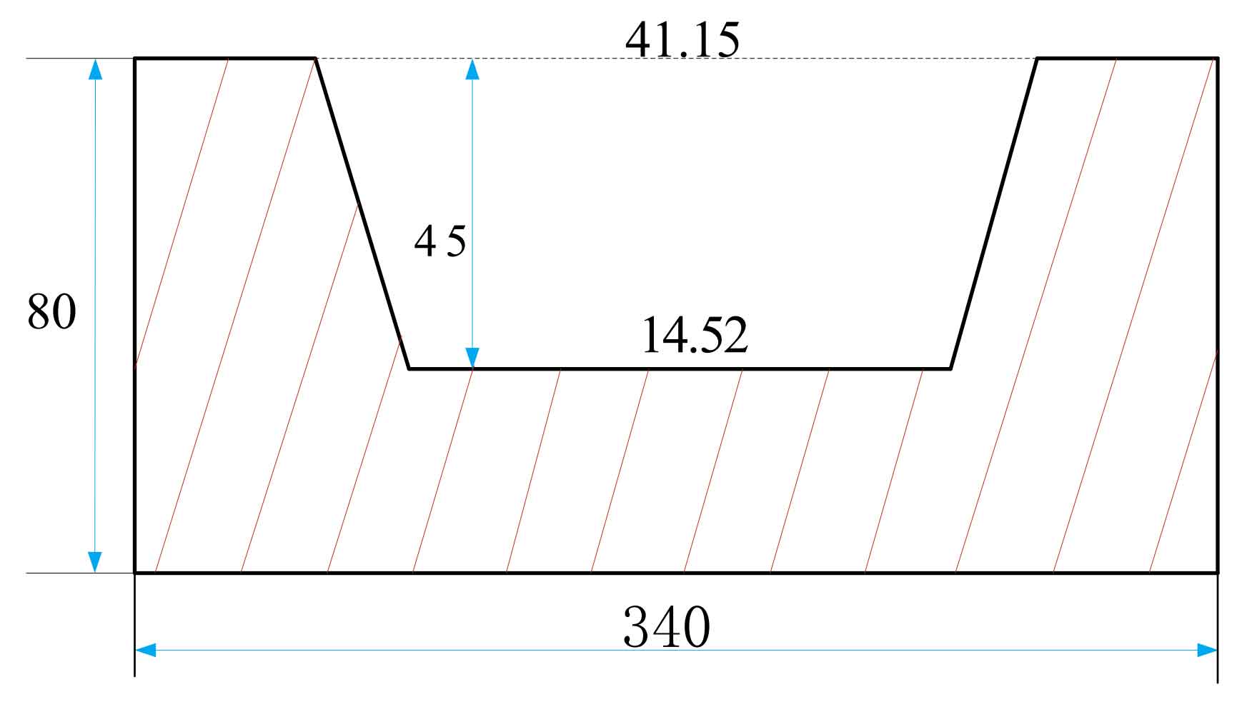
According to the model established in Figure 1, the tooth depth of the gear is consistent with the tooth height, the left and right sides of the tooth are symmetrical about the center, and the included angle between the two sides of the tooth and the thickness direction of the straight bevel gear blank is α= 73.6, the width of the top of the tooth groove is X3 = 41.15mm, and the width of the bottom of the tooth groove is x2 = 14.52mm, as shown in Figure 2.
