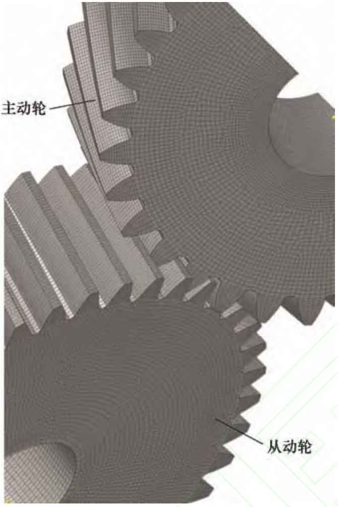
Using the parameters of the helical gear calculation in Table 1, Hypermesh preprocessing was used to partition and obtain the finite element mesh model of the helical gear pair, as shown in Figure 1. The material properties of the helical gear are defined as 17CrNiMo6, elastic modulus=206 MPa, Poisson’s ratio=0.27. The unit size of the small gear is set to a maximum of 4.2 mm and a minimum of 0.6 mm, while the unit size of the large gear is set to a maximum of 3.5 mm and a minimum of 0.4 mm. A friction coefficient of 0.1 is taken, and a speed of 20 rad/s is applied to the driving wheel, and a torque of 500 N · m is applied to the driven wheel. Perform contact stress verification analysis on helical gear pairs in the finite element analysis software ABAQUS, and extract the contact compressive stress (CPRESS) of the driving wheel with twist error at a certain moment.
| Parameters | Modified driving wheel | Driven wheel |
| Module mn/mm | 5 | 5 |
| Normal pressure angle α N/(°) | 20 | 20 |
| Spiral angle β/ (°) | 20 | 10 |
| Number of teeth z | 31 | 43 |
| Tooth width b/mm | 55 | 60 |
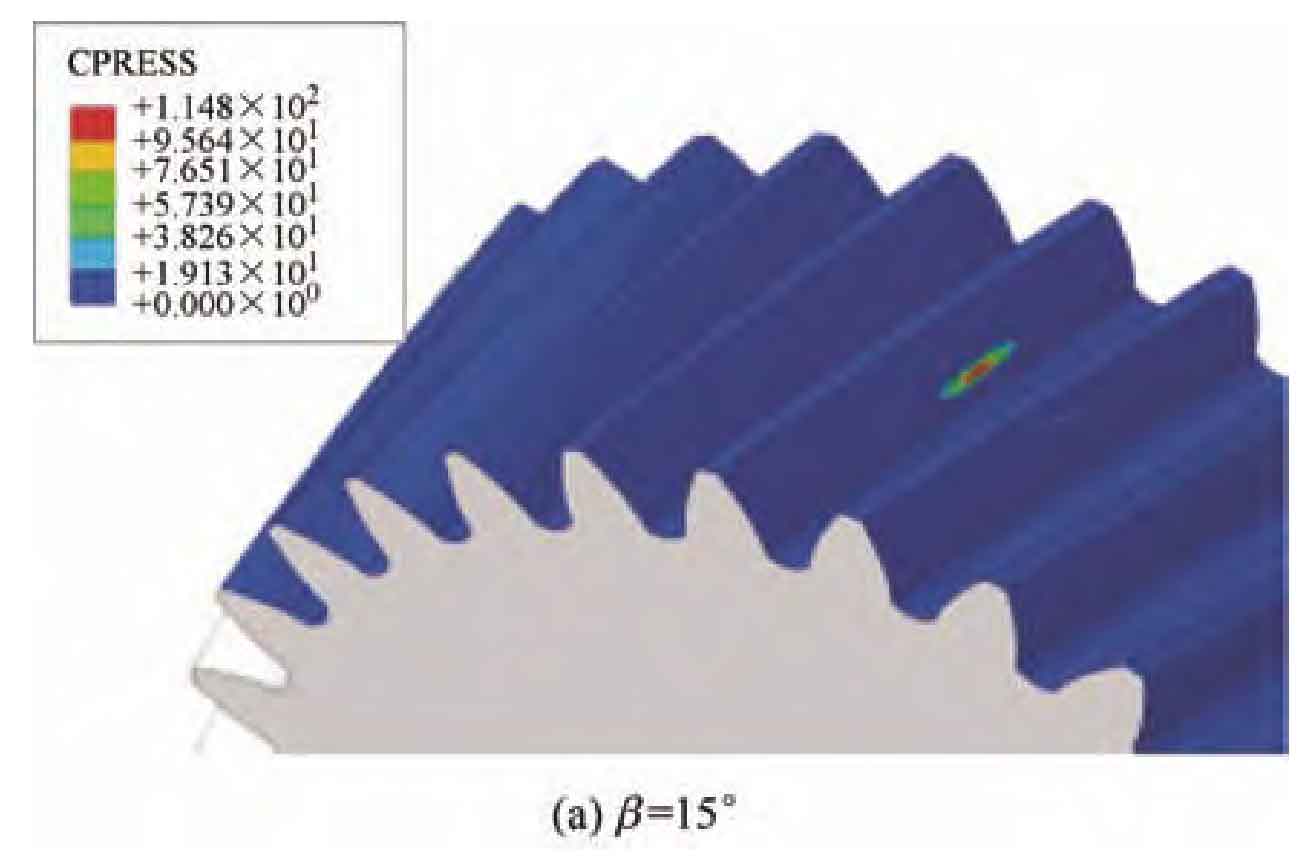
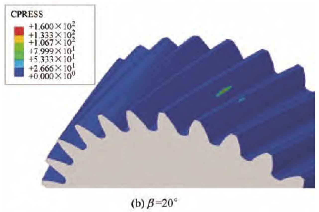
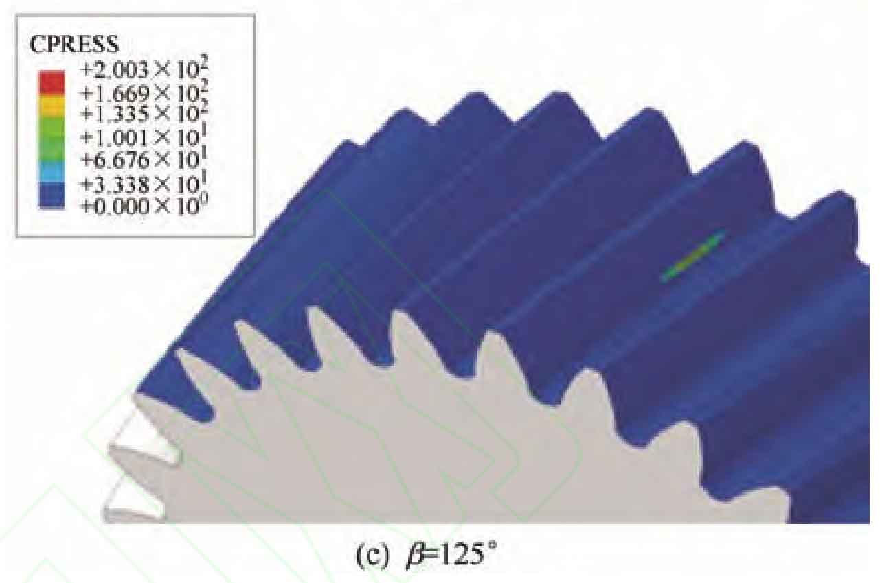
When the modification amount of the helical gear is 30 μ m. The contact marks at helix angles of 15 º, 20 º, and 25 º are shown in Figure 2, and the maximum contact stress is shown in Table 2. According to Table 2, the maximum contact stress increases with the increase of helix angle, which proves the influence of helix angle changes on the contact stress of twisted tooth surfaces and further verifies the correctness of the TCA model; When the helix angle is 25 º, the contact mark is close to the tooth root, and there may be edge contact that increases the contact stress.
| Group | Spiral angle/(°) | Maximum contact stress/MPa |
| Group 1 | 15 | 1.148×10^2 |
| Group 2 | 20 | 1.600×10^2 |
| Group 3 | 25 | 2.003×10^2 |
| Group | Spiral angle/(°) | Maximum contact stress/MPa |
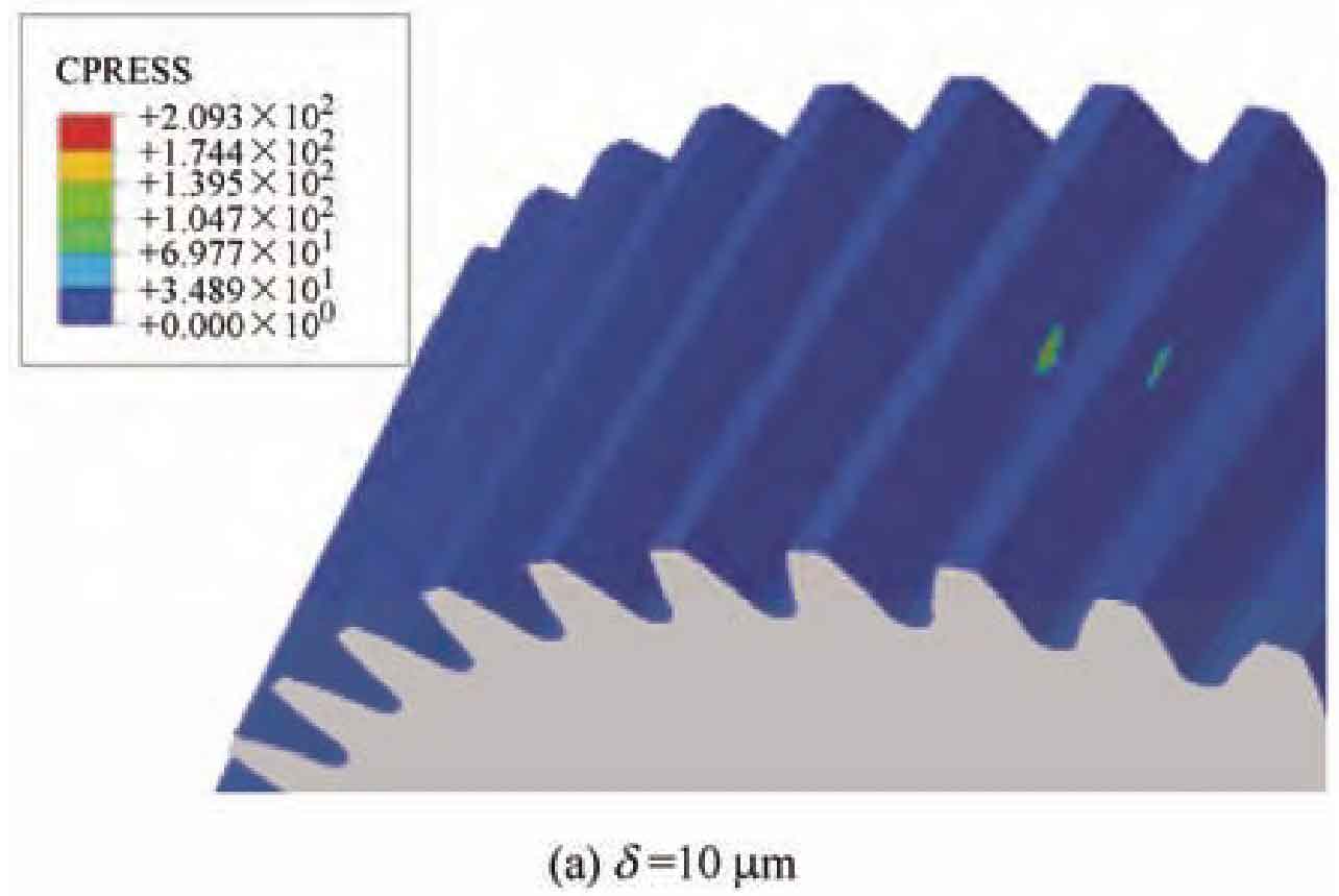
| Group 1 | 10 | 2.093×10^2 |
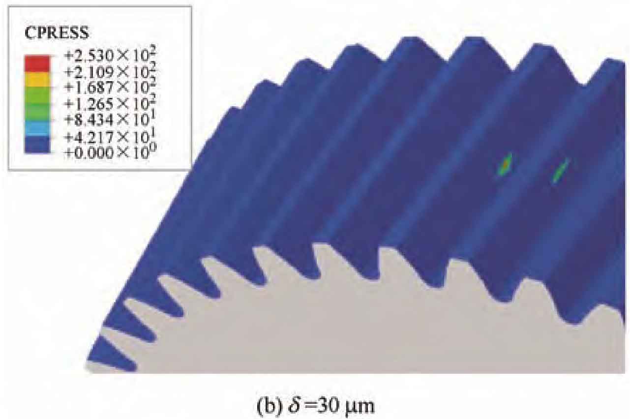
| Group 2 | 30 | 2.530×10^2 |
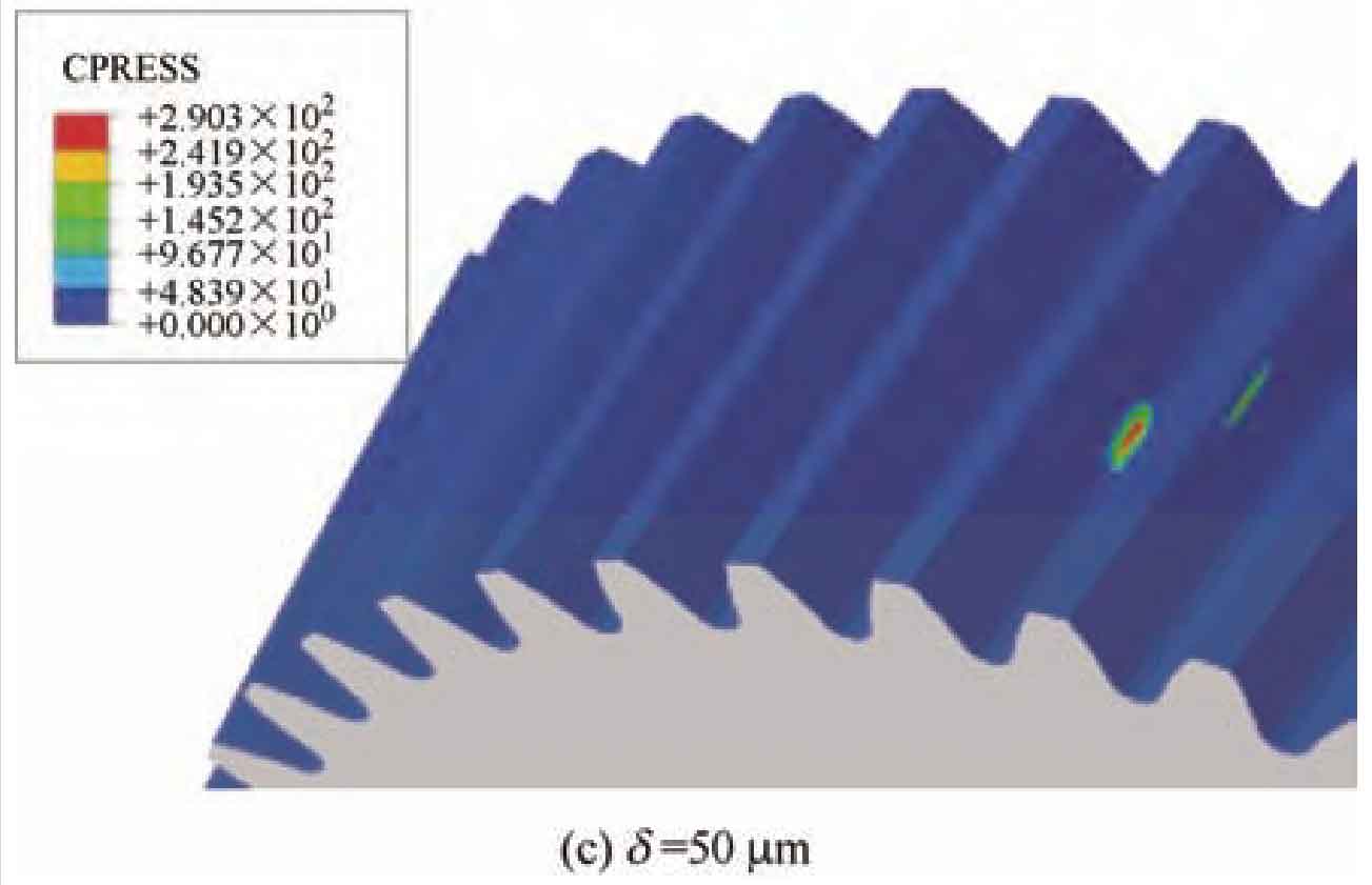
| Group 3 | 50 | 2.903×10^2 |
When the helix angle of the helical gear is 20 º, the modification amount is 10 respectively μ m. 30 μ m. 50 μ The contact imprint at m is shown in Figure 3, and the maximum contact stress is shown in Table 3. According to Table 3, as the amount of modification increases, the change in maximum contact stress is not significant, but the modification amount is 50 μ There is a noticeable edge contact in the contact imprint at time m.

