In order to verify the reliability of finite element simulation results, a coordinate grid test was carried out on a 2 mm x 2 mm semi-cylindrical lead sample.The assembly drawings of the samples, dies and dies used for the test are shown in Figure 1.

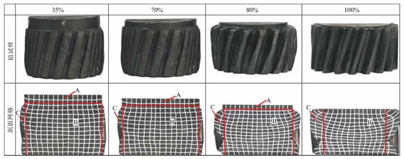
Figure 2 shows the grid changes of 35%, 70%, 80% and 100% respectively for formed parts and lead samples.In order to compare and analyze the simulation results shown in the figure, the lead sample grids with different deformations are also divided into three characteristic areas A, B and C corresponding to Figure 1, as shown in Figure 2.

From Figure 2, it can be seen that the grid deformation characteristics of lead samples are basically in agreement with the simulated results shown in the figure. Zone B is subject to axial compression-radial tensile deformation due to the axial action from the convex and concave dies.Zone C is subjected to radial and axial forces from the cavity of the concave model, and the mesh undergoes axial compression-radial tensile deformation from the middle of the tooth to both ends of the corner of the tooth.At the later stage of forming, the bending deformation of the grid in zone C towards the corners of both ends of the tooth profile becomes more intense, the axial spacing decreases and the transverse spacing increases.The flow-net function of Deform-3D software can be used to predict the streamline change characteristics of cylindrical helical gears during precision forming and reveal the material flow laws of toothed parts.
