
Because the trace of the contact area of the spiral bevel gear tooth surface has a linear change relationship, when the spiral bevel gear moves, there will be contact points on its meshing surface, and visual image tracking will be realized through linear capture and determination of contact points.
Based on the contact area image given in the above process, the image is subject to direction transformation. Let the directions be x and y, and SX and sy be the convolution directions of X and y. At this time, there is a pixel in the image with a corresponding direction angle θ 1 = arctg (SY / SX), representing the linear gradient direction without one transformation. After all the binarized points in the image are edged, the rule that the trace edges are basically located on the contact edges of the tooth surface can be obtained. According to this feature, trace tracking can be realized by capturing the specific edges of the spiral bevel gear and the contact surface.
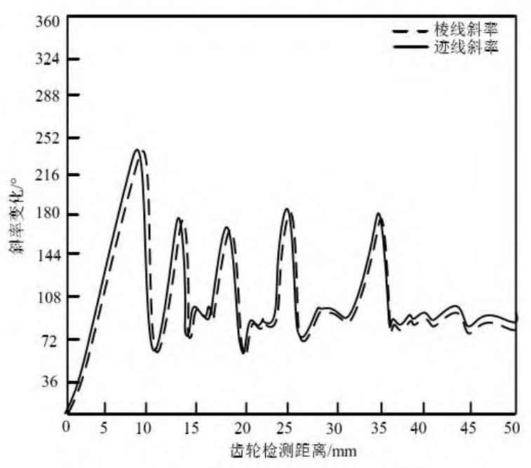
Figure 1 shows the image change law of the spiral bevel gear with the edge line in line with the trace. Let the edge line be ζ , For any tooth surface contact point P (A1, B1) in the image, there is a ridge line intersection point at that point. Determine the correlation between the edge slope and the trace by calculating the contact parameters of the intersection point ζ The calculation equation of is shown in formula (1):
The intercept formula can also be expressed as shown in formula (2):
Slope of ridge line ζ The correlation with the intersection of the contact surface is shown in formula (3):
In formula (3), a represents the contact area of the edge point in the image; F (x) indicates a positive correlation. When f (x) = 1, it represents the slope of the ridge line ζ There is a positive correlation with the contact intersection, and the intersection position can be determined to be the existing position of the trace, and the tracking target point is correct; When f (x) < 1, it means that there is an offset relationship between them. The smaller the value is, the larger the oblique offset of the ridge line and the trace line is, and the real-time position of the trace line is followed by the offset value; When f (x) = 0, it represents the slope of the ridge line ζ It is determined that the trace is not at the tracking target point.
| Contact form | Movement direction | |
| Forward contact | The contact area between gear and tooth surface is basically the same, only intermediate contact exists | The large end of the tooth surface moves toward the small end of the tooth surface |
| Positive “big” contact | The contact area between the gear and the tooth surface is basically the same, and the contact area at the middle position is larger | The large end of the tooth surface moves toward the small end of the tooth surface |
| Forward contact | The contact area between the gear and the tooth surface is basically the same, and the contact area around is large | There are signs of movement throughout the range |
| Reverse “small” contact | The contact area between the gear and the tooth surface is small, and there is a phenomenon of inclination in the small direction | The small end of the tooth surface moves toward the large end of the tooth surface |
| Reverse “big” contact | The contact area between the gear and the tooth surface is large and inclined in a large direction | The small end of the tooth surface moves toward the large end of the tooth surface |
| Contactless | Contactless | No movement direction |
Through the above process, the effective determination of trace tracking can be realized. During the movement of spiral bevel gears, the contact shape of concave and convex surfaces will also affect the occurrence point and change shape of traces. Among them, the concave contact surface is large, and the trace has a greater sense of existence, which is also easier to track and capture; The contact surface of the convex surface is too small, and the existence of traces is also small. When visual tracking is carried out, it is more difficult to capture. In order to avoid tracking differences, this paper adopts ridge line comparison to achieve tracking unity. The edge line belongs to the intersection point between the spiral bevel gear and other surfaces. Whether it is a concave surface or a convex surface, there is an edge line when it moves. By determining whether there is a positive intersection relationship between the edge line and it, the tracking quality can be guaranteed to the maximum extent and the error can be minimized.