With the development of the times, cars have become essential household items, but as the usage time increases, car gears will experience varying degrees of wear, especially the wear of the rear axle spiral bevel gears. This is due to the coupled vertical vibration of the rear axle during the driving process of the car, which leads to wear of the spiral bevel gears on the rear axle. If timely detection is not carried out, it will reduce the safety of the car’s driving. Research effective methods for detecting the wear of automotive spiral bevel gears, improve the detection accuracy of automotive spiral bevel gear wear, enhance the safety of automotive driving, and provide safety guarantees for people’s transportation.
A wear detection method for automotive spiral bevel gears is proposed based on wavelet packet energy and modulation signal bispectral sideband estimation. The wear signal of automotive spiral bevel gears is decomposed into multiple frequency bands using wavelet packet transform, and then the tooth surface wear characteristics are extracted from the wear signal through modulation signal bispectral sideband estimation method. Finally, the wear detection of automotive spiral bevel gears is completed through detection indicators. However, this method did not consider the interference of noise, resulting in insufficient accuracy in detecting the wear of automotive spiral bevel gears. Propose a wear detection method for automotive spiral bevel gears based on reverse engineering. This method is based on the principle of wear detection for automotive spiral bevel gears, constructs a transformation matrix for the wear area of automotive spiral bevel gears, and compensates for errors in the wear area. Construct a NURBS surface fitting equation with compensation points to complete the detection of wear on automotive spiral bevel gears. However, the fitting results of the wear surface of this method may show areas that are not worn, resulting in insufficient detection performance. Propose a wear detection method for automotive spiral bevel gears based on improved Mask Scoring R CNN. This method uses residual network and feature pyramid network as the backbone network, and extracts wear features of automotive spiral bevel gears through semantic information and detail feature fusion. After normalizing the local feature layer, the binary mask graphic information is calculated to complete the detection of wear on automotive spiral bevel gears. However, this method did not consider the issue of data denoising, resulting in excessive noise in the sample data and reducing the detection accuracy of automotive spiral bevel gear wear.
In order to solve the problems of the above-mentioned methods for detecting the wear of automotive spiral bevel gears, a Delaunay triangulation method for detecting the wear of automotive spiral bevel gears is proposed. Using Delaunay triangulation to process adjacent scanning lines of discrete data on the tooth surface, non characteristic discrete data on the tooth surface is divided into blocks. Using Hermite interpolation algorithm to traverse and detect the Delaunay triangulation mesh, completing the detection of wear on automotive spiral bevel gears.
1. Segmentation of non characteristic discrete data on tooth surfaces
Construct a model of automotive spiral bevel gears using NURBS (Non Uniform Rational B-Splines) surfaces, and perform non feature block processing on the surface data of automotive spiral bevel gears through Delaunay triangulation.
There are no other points within the circumcircle range of any triangle in the Delaunay triangulation network, and the nearest point forms the triangle. Regardless of where the processing starts from the tooth surface, consistent results will be obtained. Applying Delaunay triangulation to block non feature data of tooth surfaces can accurately describe the surface area of automotive spiral bevel gears, which helps to improve the detection accuracy of wear on automotive spiral bevel gears.
Using tensor product form to construct the NURBS surface of automotive spiral bevel gears, the specific expression is as follows:
In the formula: i, b – surface direction; A (i, b) – NURBS surface function; Q – number of center points in direction i; M – number of center points in direction b; Bok – Center point of the surface; No, l – spline basis function in direction i; Nk, l-spline basis function in direction b; ξ OK – Weight factor.
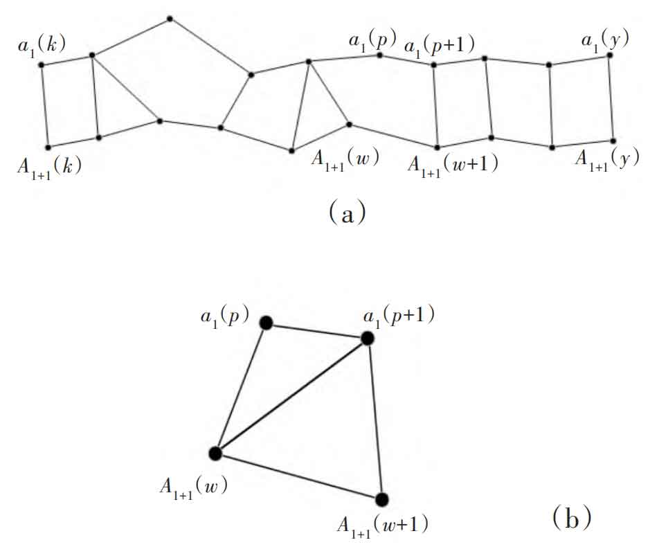
After measuring the discrete data on the surface of automotive spiral bevel gears using a scanning method, the surface discrete data is processed using the De ⁃ launay triangulation principle. set up α If i represents the scanning line, there are: i=1, 2, 3,…, n, α L, α L+1 represents two adjacent scanning lines, α L (k), k=1, 2, 3,…, y; α L+1 (K), K=1, 2, 3,…, y represents the test point, y represents the number of test points.
Connect the starting and ending points of two adjacent scanning lines, and then connect the nearest measurement point corresponding to each measurement point on the other scanning line. Divide the spatial area between the two scanning lines into several areas, as shown in Figure 1 (a). Detect the triangular and quadrilateral spatial regions, and divide the quadrilateral spatial regions based on the minimum inner angle maximum criterion, ultimately completing the Delaunay triangulation, as shown in Figure 1 (b).
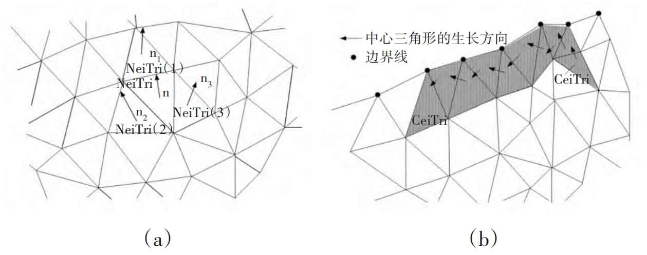
By Delaunay triangulation, non feature discrete data on the tooth surface is processed into blocks. Any triangle on the NURBS tooth surface model is selected as the center triangle CenTri, and all center triangle values are calculated. The formula is as follows:
In the formula: n=1, 2, 3, ε N – the angle between two triangles; Y – Value of the center triangle region.
Select the center triangle with the smallest region value as the starting triangle, as shown in Figure 2 (a). Select the adjacent triangle with the smallest angle to the starting triangle as the center triangle. If equation (2) is satisfied, exclude the starting center triangle, calculate the degree of angle between the surrounding triangles and the starting triangle, and take the triangle with the smallest degree as the center triangle. Otherwise, continue to reselect the starting triangle. According to the above operation, traverse all triangles to complete the non characteristic discrete data segmentation of the automotive spiral bevel gear, as shown in Figure 2 (b).
Calculate tooth surface data through triangular interpolation algorithm to achieve a comprehensive description of the surface area of automotive spiral bevel gears.
2. Wear detection of automotive spiral bevel gears using Hermite interpolation algorithm
In order to accurately detect the wear area of automotive spiral bevel gears, an algorithm is used to detect tooth surface wear based on the non characteristic discrete data block results mentioned above. The specific detection steps for Hermite are as follows: Local mean decomposition in interpolation algorithm:
(1) Set the original discrete data to c (y) and transform the original strongly noisy discrete data c (y) into small parameter data.
(2) In the cascaded bistable stochastic resonance (CBSR) system, the small parameter data obtained in step (1) is denoised to obtain the denoised discrete data cn (y).
(3) Extend the extremum point ml of the denoised discrete data to obtain a new sequence cl.
(4) Starting from one end of the new sequence, select the maximum or minimum point on it, and generate two envelope lines using the Hermite interpolation algorithm.
(5) Calculate the local mean function using the following formula:
In the formula: q (y) – local mean function; Rup (y) – upper envelope line; Rdown (y) – Lower envelope line.
(6) Calculate the envelope estimation function using the following formula:
In the formula: s (y) – envelope estimation function.
(7) The LMD analysis method will be used to separate the envelope data from the original tooth surface data, and the amplitude of the PF (product function) component will be calculated based on the envelope data. The formula is as follows:
In the formula: fo (y) – PF component amplitude, the value range of fo (y) is [0,1]. If the calculation result of equation (5) is not within the value range, it is determined that wear has occurred in that area. Process the triangular meshes of all automotive spiral bevel gears infinitely according to the above steps until all triangular meshes have completed traversal detection.
3. Experimental analysis
To verify the effectiveness of the Delaunay triangulation method for detecting the wear of automotive spiral bevel gears, comparative testing experiments were conducted.
This study selected the 2015 Santana manual car spiral bevel gear as the research object, and selected 20 spiral bevel gears of the same car for research. The spiral bevel gears of the car work smoothly, have a large transmission ratio, transmit power greatly, and have a compact structure, which can meet the needs of this experiment.
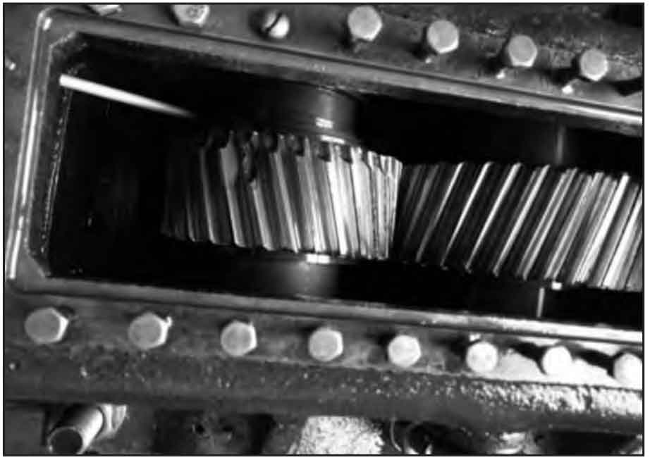
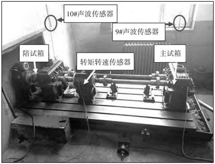
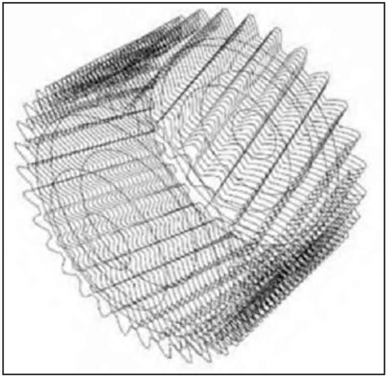
The material properties of spiral bevel gears for automobiles are shown in Table 1. The equipment used in this experiment is shown in Figure 3. The wear of automotive spiral bevel gears is shown in Figure 4. The Delaunay triangulation results of worn automotive spiral bevel gears are shown in Figure 5.
| Parts | Material | Density (kg/m3) | Young’s modulus (GPa) | Poisson’s ratio |
| Gear | 45Cr | 7850 | 206 | 0.3 |
Based on the experimental equipment and material property data mentioned above, in order to obtain more accurate experimental results, the experimental process is planned. The specific experimental process is:
(1) Maintain the continuous operation of the automotive spiral bevel gear wear experimental equipment, with a running time of 200 hours. Collect wear data of the automotive spiral bevel gear within 200 hours, with a time interval of 5 minutes. Within one hour, 12 sets of wear data can be collected.
(2) The testing indicators for this experiment are set as the depth of wear of automotive spiral bevel gears, the wear rate of automotive spiral bevel gears, and the detection accuracy of wear area.
(3) Choose the proposed reverse engineering based detection method and the proposed improved Mask Scoring R-CNN based detection method as the comparative methods for this experiment.
(4) According to the set experimental indicators, three different methods were used for experimental verification.
3.1 Wear depth of automotive spiral bevel gears
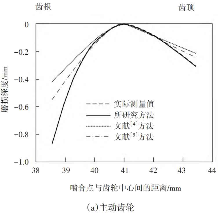
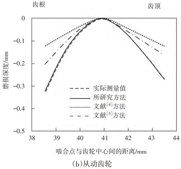
The wear of automotive spiral bevel gears is mainly between the driving gear and the driven gear, and the depth of wear of automotive spiral bevel gears will change with the increase of operating time. The wear depth results of the driving gear and the driven gear are shown in Figure 6.
In Figure 6, the wear depth of 0 is the initial surface state, and the positions with higher wear degree of the automotive spiral bevel gear are the tooth top and root. Comparing the wear depth detection results of the three methods with the actual results, it was found that the wear depth results of the studied method were basically consistent with the actual measurement, while the wear depth values of the method differed significantly from the actual measurement results. Therefore, it indicates that the research method can effectively analyze the wear depth of automotive spiral bevel gears.
3.2 Wear rate of automotive spiral bevel gears
The wear rate of automotive spiral bevel gears refers to the amount of wear of automotive spiral bevel gear materials per unit time, which can effectively reflect the wear situation of automotive spiral bevel gears. Therefore, the wear rate detection results of the three methods are compared and analyzed with the actual wear rate calculation results. The wear rate results are shown in Figure 7.
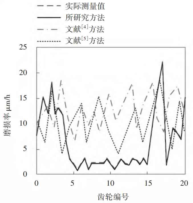
From the comparison results of the wear rate of automotive spiral bevel gears shown in Figure 7, it can be seen that during the study of 20 automotive spiral bevel gears, the wear rate of the research method remained consistent with the actual wear rate, with a maximum error of no more than 0.01 μ m. The wear rate of the method differs significantly from the actual wear rate. Therefore, it indicates that the research method can obtain more accurate results on the wear rate of automotive spiral bevel gears, and can improve the detection effect of automotive spiral bevel gear wear.
3.3 Measurement accuracy of wear area of automotive spiral bevel gears
In order to further verify the wear detection performance of the research method for automotive spiral bevel gears, the accuracy of detecting the wear area of automotive spiral bevel gears is taken as the indicator, and the research method is also compared and verified with the literature method. Each experiment was conducted to detect the wear area of 20 automotive spiral bevel gears. A total of 10 experiments were conducted, and the average results of the wear area detection for each experiment are shown in Table 2.
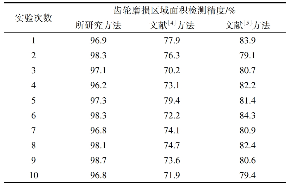
From the comparison results of the wear area detection accuracy of automotive spiral bevel gears shown in Table 2, it can be seen that the comparison method has the highest wear area detection accuracy of 98.7%, while the two comparison methods have the highest wear area detection accuracy values of 79.4% and 84.3%, respectively. Therefore, it indicates that the research method can accurately detect the area of wear on automotive spiral bevel gears.
4. Conclusion
The detection of wear on automotive spiral bevel gears is beneficial for the safety of driving and has significant practical significance for the safe and stable operation of automobiles. Therefore, a Delaunay triangulation method for detecting wear on automotive spiral bevel gears is proposed. Perform Delaunay triangulation on adjacent scanning lines of the tooth surface to complete the segmentation of non feature discrete data on the tooth surface. Based on the segmentation results, Hermite interpolation is used to calculate the PF component replication, and all triangular meshes are traversed to complete the detection of the wear area.
The experimental data shows that the wear depth and wear rate results of the proposed method are basically consistent with the actual values, and can accurately detect the wear area, with a maximum detection accuracy of 98.7%. Effectively solving the problems existing in traditional methods, injecting fresh blood into the wear detection technology of automotive spiral bevel gears.

