
In my years of experience maintaining industrial transmission systems, I have found that worm gear reducers are indispensable for low-speed, high-torque applications. They are widely used in chemical processing, material handling, packaging, and automated production lines. Despite their robustness, these reducers are prone to specific failures due to the sliding contact between the worm and worm wheel. Through systematic investigation and field practice, I have compiled the common failure modes, root causes, and effective corrective actions. This article presents a comprehensive analysis based on my hands-on work with RV-series worm gear reducers, emphasizing the use of tables and quantitative formulas to guide diagnosis and maintenance.
1. Overview of Worm Gear Reducers
1.1 Operational Characteristics
Worm gear reducers provide high speed reduction ratios in a compact package. The fundamental relationship between input speed n1 (worm) and output speed n2 (worm wheel) is given by the transmission ratio i:
$$ i = \frac{n_1}{n_2} = \frac{z_2}{z_1} $$
where z1 is the number of worm threads (typically 1–6) and z2 is the number of teeth on the worm wheel. The mechanical efficiency η depends on the lead angle γ and the friction angle ρ:
$$ \eta = \frac{\tan\gamma}{\tan(\gamma + \rho)} $$
In my practice, I have observed that efficiency drops significantly when the lead angle is small, leading to higher heat generation. The torque transmitted T2 at the output shaft is:
$$ T_2 = T_1 \cdot i \cdot \eta $$
where T1 is the input torque. These fundamental equations help me quickly assess whether a reducer is operating within its design limits.
1.2 Mechanical Structure
The RV-series worm gear reducer consists of several key components. 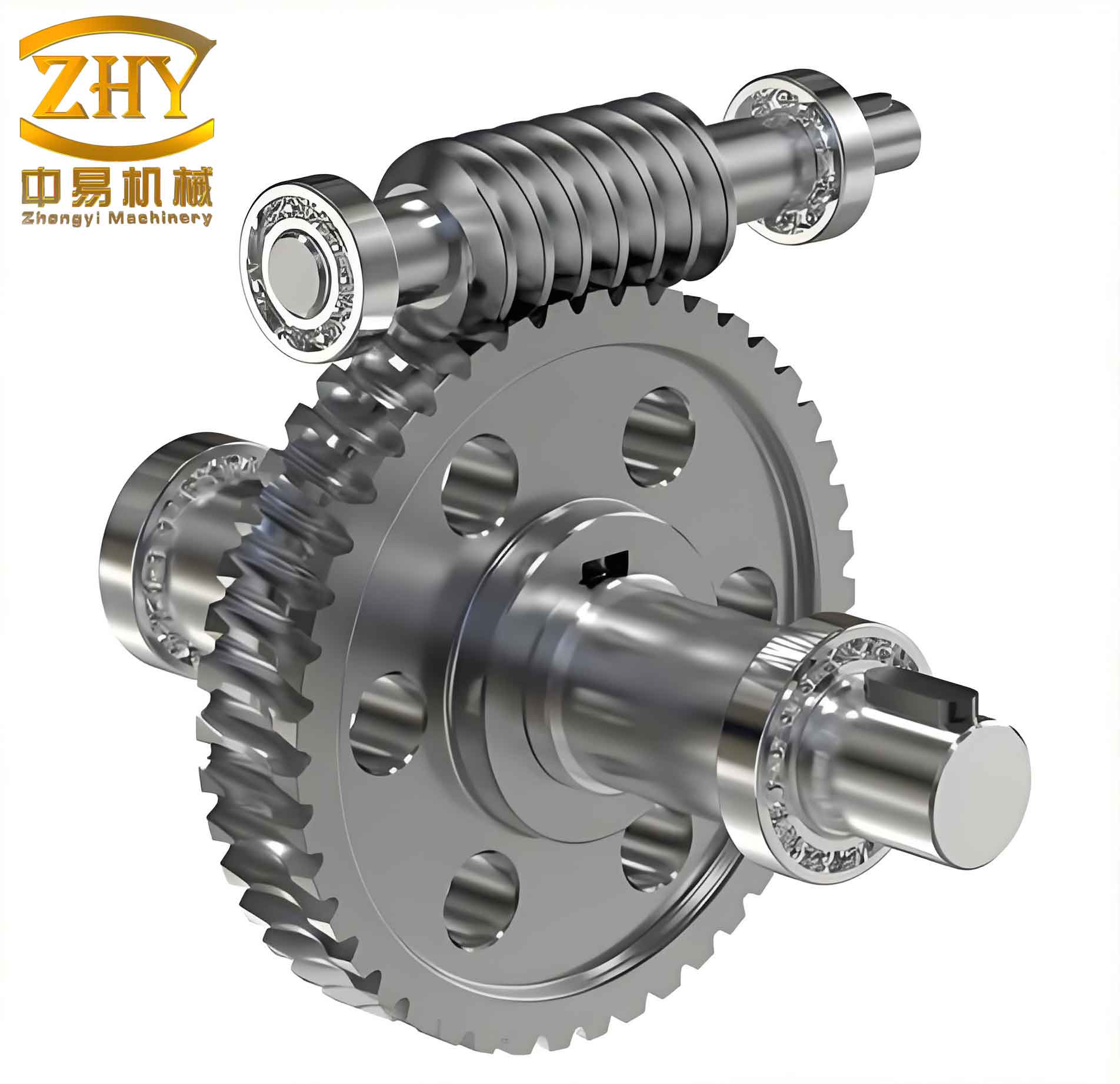 The main parts include the worm shaft, oil seals, flange, bearings, housing, retaining rings, seal covers, worm wheel, and oil drain plug. The housing is typically made of cast aluminum alloy (ZL401) for light weight and good heat dissipation. Oil seals are usually nitrile rubber or fluororubber to resist high temperature and oil corrosion. Bearings are roller bearings supporting the worm shaft. The following table summarizes the materials and functions of critical parts:
| Component | Material | Function |
|---|---|---|
| Worm shaft | 40Cr, 20CrMnTi (case-hardened) | Transmit rotary motion from motor |
| Worm wheel | ZCuSn10P1 (tin bronze), ZCuAl10Fe3 (aluminum bronze) | Reduce speed and increase torque |
| Housing | ZL401 (cast aluminum) | Support components, dissipate heat |
| Oil seal | NBR, FKM | Prevent lubricant leakage |
| Bearings | Roller bearing steel | Support worm shaft with low friction |
| Oil drain plug | Carbon steel | Drain used lubricant |
1.3 Worm Drive Types
Based on the geometry of the worm, I classify worm drives into three main categories. Each type exhibits distinct performance characteristics:
| Type | Geometry | Efficiency | Load Capacity | Typical Applications |
|---|---|---|---|---|
| Cylindrical (Archimedes) | Axial tooth profile straight; transverse profile Archimedes spiral | Moderate | Moderate | General industrial drives |
| Involute cylindrical | Tooth surface is involute helicoid | High | High | High-speed, precision drives |
| Toroidal (hourglass) | Worm envelops the wheel | Very high | Very high | Heavy-duty, high-power transmissions |
In my field work, I most frequently encounter the cylindrical Archimedes type because of its low manufacturing cost, though toroidal drives are preferred when space is constrained and high torque is required.
1.4 Materials for Worm and Worm Wheel
The wear resistance of worm gears directly depends on material pairing. The worm is usually made of hardened steel (e.g., 40Cr surface-hardened to 45–55 HRC, or 20CrMnTi carburized to 56–62 HRC) while the worm wheel is made of a softer alloy such as tin bronze ZCuSn10P1. I have also successfully used zinc-aluminum alloy ZA27 as a cost-effective alternative. The wear rate Wv (volume loss per sliding distance) can be approximated by Archard’s wear law:
$$ W_v = k \frac{F \cdot s}{H} $$
where F is the normal load, s is the sliding distance, H is the hardness of the softer material, and k is the wear coefficient. My experience with ZA27 has shown that its wear rate is comparable to tin bronze but with 25–30% lower material cost and 3–5 times longer service life under proper lubrication.
| Material | Tensile Strength (MPa) | Max Sliding Speed (m/s) | Wear Resistance | Cost |
|---|---|---|---|---|
| ZCuSn10P1 (tin bronze) | 250–350 | >3 | Excellent | High |
| ZCuAl10Fe3 (aluminum bronze) | 500–600 | <4 | Good | Moderate |
| Gray cast iron | 150–250 | <2 | Poor | Low |
| ZA27 (zinc-aluminum) | 400–450 | <3 | Very Good | Low–Moderate |
1.5 Application Fields
Worm gear reducers are ubiquitous in industries requiring compact, high-ratio drives. I have serviced them in:
- Metallurgical rolling mills (screw-down mechanisms, coilers)
- Marine winches and anchor handling equipment
- Chemical agitators and mixers
- Packaging and blow-molding machines
- Overhead cranes and hoists
- Construction personnel lifts and gondolas
2. Common Failure Modes of Worm Gear Reducers
From my maintenance logs, I have categorized the five most frequent failure symptoms: overheating, oil leakage, vibration, worm gear wear, and abnormal noise. Each symptom has specific root causes that I will discuss with diagnostic tables and supporting formulas.
2.1 Overheating
Excessive heat generation shortens lubricant life, degrades seals, and accelerates wear. The heat source is primarily sliding friction and power losses. The heat balance can be expressed as:
$$ Q_{gen} = P_{in} (1 – \eta) $$
$$ Q_{diss} = h_c A (T_{oil} – T_{amb}) $$
where Qgen is the heat generated, Pin is input power, η is efficiency, hc is convective heat transfer coefficient, A is housing surface area, Toil is oil temperature, and Tamb is ambient temperature. I have developed the following troubleshooting guide:
| Cause | Root Explanation | Solution |
|---|---|---|
| Misalignment between reducer and driven machine | Creates additional radial loads and friction | Realign shafts using dial indicator; ensure coaxiality within 0.05 mm |
| Overload operation | Exceeds rated torque, increasing sliding friction | Reduce load; check motor current and compare with nameplate |
| Excessive oil seal friction | Dry or deformed lip increases torque | Apply a few drops of oil on seal lip before start-up; replace if worn |
| Incorrect oil level (too low or too high) | Low level causes starvation; high level causes churning loss | Maintain oil at midpoint of sight glass |
| Contaminated or degraded oil | Increases friction and reduces heat dissipation | Drain and flush; refill with specified grade (e.g., ISO VG 460 synthetic) |
In one case, a reducer in a conveyor system reached 95°C (normal max 80°C). After realigning the motor and reducer shafts, the temperature dropped to 70°C within one hour.
2.2 Oil Leakage
Leakage not only wastes lubricant but also creates safety hazards and allows contaminants to enter. I have identified the following common sources:
| Cause | Inspection Point | Solution |
|---|---|---|
| Worn or hardened oil seal lip | Visual: cracks, flat spots on lip | Replace seal; ensure correct size (e.g., TC 35×62×8) |
| Shaft surface wear at seal contact area | Measure shaft diameter with micrometer; check for grooves | Polish with fine emery paper; if worn >0.2 mm, replace shaft or use wear sleeve |
| Loose drain plug or missing sealing compound | Check plug torque and condition of copper washer | Apply Loctite 577; torque to 30 Nm |
| Cracked or broken oil sight glass | Visual: oil film or bubbles around sight | Replace sight glass unit |
| Damaged housing gasket (if applicable) | Check joint surfaces | Clean and apply anaerobic sealant; replace gasket |
The leakage rate q through a worn seal can be estimated by:
$$ q = \frac{\pi D h^3 \Delta p}{12 \mu L} $$
where D is shaft diameter, h is average clearance, Δp is pressure difference, μ is dynamic viscosity, and L is seal contact length. Even a small increase in clearance dramatically increases leakage.
2.3 Vibration
Excessive vibration accelerates bearing and gear fatigue. I measure vibration velocity (mm/s RMS) using a handheld vibrometer. Acceptable levels for worm gear reducers are below 4.5 mm/s according to ISO 10816-3. The causes are:
| Cause | Typical Frequency Signature | Solution |
|---|---|---|
| Loose foundation bolts | 1× input speed | Tighten all bolts to specified torque; use spring washers |
| Worm gear tooth wear or pitting | Mesh frequency (number of worm starts × input speed) | Replace worm gear set or remanufacture if cost-effective |
| Bearing damage (pitting, spalling) | Ball/roller pass frequencies | Replace bearing; check lubrication and alignment |
| Imbalance of fan or coupling | 1× input speed (dominant) | Dynamic balance; offset weight |
For example, when a reducer exhibited 7.2 mm/s at 1500 rpm input, I found the motor-reducer coupling had a 0.3 mm radial offset. After correction, vibration dropped to 2.1 mm/s.
2.4 Worm Gear Wear
This is the most common failure mode I encounter. Wear leads to increased backlash, loss of efficiency, and eventually tooth breakage. The wear rate follows Archard’s law as mentioned earlier. Factors under my control are lubrication, load, and cleanliness. The following table summarizes the root causes:
| Cause | Effect on Wear | Solution |
|---|---|---|
| Overload | Increases contact stress; violates Hertzian contact limit | Reduce load or use higher rating unit |
| Incorrect lubricant viscosity or type | Film thickness insufficient; boundary lubrication regime | Select EP gear oil with correct viscosity (e.g., ISO VG 320 for moderate loads) |
| Insufficient lubricant quantity | Local dry contact; rapid adhesive wear | Check oil level weekly; top up with same grade |
| Extended oil change intervals | Oil oxidation; abrasive particles accumulate | Change oil every 2000–3000 operating hours or per OEM recommendation |
| High operating temperature | Oil viscosity drops; film collapses | Improve cooling; check for preceding overheating causes |
I have developed a simple wear estimation formula for worm wheels based on field data:
$$ h_w = k_w \cdot \frac{P \cdot t}{A_c} $$
where hw is average wear depth (mm), kw is a wear coefficient (1.5×10⁻⁶ mm3/N·m for tin bronze under good lubrication), P is transmitted power (kW), t is operating time (hours), and Ac is contact area (mm2). Using this, I predict remaining life and schedule replacements proactively.
2.5 Abnormal Noise
Noise can be a symptom of meshing problems, bearing damage, or cavitation. I classify noise by its character: whining (gear mesh), rattling (backlash), or grinding (bearing). The troubleshooting table is:
| Cause | Sound Characteristic | Solution |
|---|---|---|
| Misalignment of reducer and driven machine | Cyclic whining at mesh frequency | Realign using laser alignment tool |
| Bearing clearance excessive or race damaged | Rumbling or knocking at multiples of shaft speed | Replace bearing; set preload correctly |
| Worm gear tooth profile errors or spalling | Harsh grinding or clicking with varying load | Replace worm gear set; if minor, dress with abrasive stone |
| Low oil level | Whining intensified; higher pitch | Add oil to correct level |
In one instance, a reducer emitted a rhythmic knocking sound. Disassembly revealed that one tooth of the worm wheel had a small chip. After replacing the worm wheel, the noise disappeared.
3. Preventive Maintenance Recommendations
Based on my long-term service experience, I recommend the following maintenance practices to maximize the life of worm gear reducers:
- Ambient temperature: Keep operating environment between –10°C and +40°C. Use synthetic oil if temperatures exceed 50°C.
- Seal care: For reducers stored or idle for 4–6 months, replace oil seals because rubber ages and loses elasticity. Before restart, manually rotate the input shaft to redistribute seal lubricant.
- Oil level and quality check: Inspect weekly via sight glass. If oil appears milky or contains metal particles, replace immediately. Use the following oil change schedule based on operating hours:
| Operating Conditions | Oil Change Interval (hours) |
|---|---|
| Clean, moderate load, ≤40°C ambient | 3000 |
| Dusty, heavy load, or high ambient temperature | 2000 |
| Continuous operation, shock loads | 1000–1500 |
Lubricant selection: I always use synthetic polyalphaolefin (PAO) or polyglycol (PAG) oils that provide a higher viscosity index and better film strength. For RV reducers, ISO VG 320 or 460 is typical.
Bearing replacement: I replace rolling bearings every 10,000 hours or whenever vibration exceeds 4.5 mm/s. When replacing, I apply the correct preload using shims or locknuts.
Alignment: I perform laser alignment during every major overhaul. Acceptable offset tolerance is 0.08 mm parallel and 0.05 mm angular. Misalignment is the leading cause of premature seal and bearing failure in my records.
Torque check: I tighten all housing bolts, foot bolts, and drain plugs to manufacturer specifications using a torque wrench.
4. Conclusion
Worm gear reducers are vital components in numerous industrial drives that require high torque and compactness. Through my years of hands-on maintenance, I have found that the most common failures—overheating, leakage, vibration, wear, and noise—can be systematically diagnosed and addressed using the tables, formulas, and procedures presented here. By adhering to a rigorous preventive maintenance program, especially regarding lubrication quality, alignment, and seal integrity, the service life of worm gears can be extended significantly. Regular monitoring of temperature, vibration, and oil condition allows me to intervene before catastrophic failure occurs, ensuring safe and reliable operation of critical machinery.